|
数据搜索系统,热门电子元器件搜索 |
|
|
数据搜索系统,热门电子元器件搜索 |
|
P9242-R 数据表(PDF) 6 Page - Renesas Technology Corp |
|
|
|||||||||||||||||||||||||||||
P9242-R 数据表(HTML) 6 Page - Renesas Technology Corp |
|
|
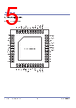
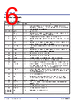
6 / 38 page  P9242-R Datasheet © 2018 Integrated Device Technology, Inc 6 January 16, 2018 2. Pin Descriptions Table 1. Pin Descriptions Pins Name Type Function 1 EN Input Active-LOW enable pin. When connected to logic HIGH, the P9242-R enters the Shut Down Mode, which has a typical current consumption of 25μA. When connected to logic LOW, the device is in normal operation. 2, 6, 34, 41, EP GND – Ground connection. 3 PREG Output Regulated 5V output used for internal device biasing. Connect a 1μF capacitor from this pin to ground. This pin must not be externally loaded. 4 VIN Input Input power supply. Connect a 10μF capacitor from this pin to ground. 5 SW_S Output Step-down regulator`s switch node. Connect one of the terminals of the 4.7μH inductor to this pin. 7 LDO33 Output Regulated 3.3V output used for internal device biasing. Connect a 1μF capacitor from this pin to ground. This pin should not be externally loaded. 8 VIN_LDO Input Linear regulator input power supply. Connected this pin to the 5V output of the step-down regulator. 9 LDO18 Output Regulated 1.8V output used for internal device biasing. Connect a 1μF capacitor from this pin to ground. This pin should not be externally loaded. 10 LED1 Input Open-drain output. Connect an LED to this pin 11 LED2 Open-drain output. Connect an LED to this pin. 12 VDDIO Input Input power supply for internal biasing. This pin must be connected to LDO33. 15 SCL Input I2C interface clock input. Connect a 5.1kΩ pull-up resistor to LDO33 rail. 16 SDA I/O I2C interface data input and data output, connect a 5.1kΩ pull-up resistor to LDO33 rail. 17 ILIM/FOD Input Programmable over-current limit and foreign object detection pin. Connect the center tap of the resistor divider to this pin to set the current-limit threshold and FOD threshold. For more information on setting the current limit and FOD, see section 7.2. 18 LED/Q-Fact Input Programmable LED pattern selection and Q-factor enable/disable. Connect the center tap of a resistor divider to this pin. For more information on setting the LED pattern and Q- factor enable/disable, see section 7.9. 19 VCOIL Input Input for coil voltage sensing. 20 TS Input Remote temperature sensor for over-temperature shutdown. Connect to the NTC thermistor network. If not used, connect to the LDO33 pin through the 10kΩ resistor. 21 BUZR Output Buzzer output. Connect a buzzer to this pin. 22 OVP_CTL I/O Logic HIGH during power transfer phase used to scale down the voltage to detect over- voltage for VCOIL pin. 23 Q_DRV1 I/O Control signal for Q factor measurement circuit. 24 Q_DRV2 I/O Control signal for Q factor measurement circuit. 13, 14, 25, 26, 27, 28, 29, 42, 43 RSV – Reserved for internal use. Do not connect. |
|
链接网址 |
| ALLDATASHEET是否为您带来帮助? [ DONATE ] |
关于 Alldatasheet | 广告服务 | 联系我们 | 隐私政策 | 数据表链接 | 链接交换 | 制造商名单 All Rights Reserved©Alldatasheet.com |
| Russian : Alldatasheetru.com | Korean : Alldatasheet.co.kr | Spanish : Alldatasheet.es | French : Alldatasheet.fr | Italian : Alldatasheetit.com Portuguese : Alldatasheetpt.com | Polish : Alldatasheet.pl | Vietnamese : Alldatasheet.vn Indian : Alldatasheet.in | Mexican : Alldatasheet.com.mx | British : Alldatasheet.co.uk | New Zealand : Alldatasheet.co.nz |
|
Family Site : ic2ic.com |
icmetro.com |
 Chinese ▼
 English
 Chinese
 German
 Japanese
 Russian
 Korean
 Spanish
 French
 Italian
 Portuguese
 Polish
 Vietnamese
 Indian
 Mexican
 British
 New Zealand