|
数据搜索系统,热门电子元器件搜索 |
|
|
数据搜索系统,热门电子元器件搜索 |
|
ADL5385ACPZ-R2 数据表(PDF) 17 Page - Analog Devices |
|
|
|||||||||||||||||||||||||||||
ADL5385ACPZ-R2 数据表(HTML) 17 Page - Analog Devices |
|
|
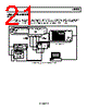
17 / 24 page  ADL5385 Rev. 0 | Page 17 of 24 –50 –90 –85 –80 –75 –70 –65 –60 –55 48 40 41 42 43 44 45 46 47 –24 –10 –12 –14 –16 –18 –20 –22 CARRIER POWER (dBm) ACPR1 (750kHz) ACPR2 (5.25MHz) ACPR3 (6.00MHz) MER Figure 38. ACP1, ACP2, ACP3, and Modulation Error Ratio (MER) vs. Output Power for 256 QAM Transmitter SPECTRAL PRODUCTS FROM HARMONIC MIXING For broadband applications such as cable TV head-end modulators, special attention must be paid to harmonics of the LO. Figure 39 shows the level of these harmonics (out to 3 GHz) as a function of the output frequency from 50 MHz to 1000 MHz, in a single-sideband (SSB) test configuration, with a baseband signal of 1 MHz and a SSB level of approximately −5 dBm. To read this plot correctly, first pick the output frequency of interest on the trace called POUT. The associated harmonics can be read off the harmonic traces at multiples of this frequency. For example, at an output frequency of 500 MHz, the fundamental power is −5 dBm. The power of the second (P2fc−BB) and third (P3fc+BB) harmonics is −63 dBm (at 1000 MHz) and −16 dBm (at 1500 MHz), respectively. Of particular importance are the products from odd-harmonics of the LO, generated from the switching operation in the mixers. For cable TV operation at frequencies above approximately 500 MHz, these harmonics fall out of the band and can be filtered by a fixed filter. However, as the frequency drops below 500 MHz, these harmonics start to fall close to or inside the cable band. This calls for either limitation of the frequency range to above 500 MHz or the use of a switchable filter bank to block in-band harmonics at low frequencies. 0 –90 0 1000 OUTPUT FREQUENCY (MHz) –80 –70 –60 –50 –40 –30 –20 –10 100 200 300 400 500 600 700 800 900 POUT P7LO + BB P5LO – BB P3LO + BB P6LO – BB P4LO + BB P2LO – BB Figure 39. Spectral Components for Output Frequencies from 50 MHz to 1000 MHz RF SECOND-ORDER PRODUCTS A two-tone RF output signal produces second-order spectral components at sum and difference frequencies. In broadband systems, these intermodulation products fall inside the carrier or in the adjacent channels. Output second-order RF intermodulation intercept is defined as OIP2_RF = POUT + (POUT − PIM(RF)) where PIM(RF) is the level of the intermodulation product at FOUT1 + FOUT2. OIP2_RF levels from a two-tone test are plotted as a function of carrier frequency in Figure 40, where the baseband tones are 3.5 MHz and 4.5 MHz at −5 dBm each. 70 0 0 2250 OUTPUT FREQUENCY (MHz) 60 50 40 30 20 10 2000 1750 1500 1250 1000 750 500 250 Figure 40. Output Second-Order Intermodulation vs. Carrier Frequency |
|
|
链接网址 |
| ALLDATASHEET是否为您带来帮助? [ DONATE ] |
关于 Alldatasheet | 广告服务 | 联系我们 | 隐私政策 | 数据表链接 | 链接交换 | 制造商名单 All Rights Reserved©Alldatasheet.com |
| Russian : Alldatasheetru.com | Korean : Alldatasheet.co.kr | Spanish : Alldatasheet.es | French : Alldatasheet.fr | Italian : Alldatasheetit.com Portuguese : Alldatasheetpt.com | Polish : Alldatasheet.pl | Vietnamese : Alldatasheet.vn Indian : Alldatasheet.in | Mexican : Alldatasheet.com.mx | British : Alldatasheet.co.uk | New Zealand : Alldatasheet.co.nz |
|
Family Site : ic2ic.com |
icmetro.com |
 Chinese ▼
 English
 Chinese
 German
 Japanese
 Russian
 Korean
 Spanish
 French
 Italian
 Portuguese
 Polish
 Vietnamese
 Indian
 Mexican
 British
 New Zealand