|
数据搜索系统,热门电子元器件搜索 |
|
|
数据搜索系统,热门电子元器件搜索 |
|
ADL5519ACPZ-R2 数据表(PDF) 23 Page - Analog Devices |
|
|
|||||||||||||||||||||||||||||
ADL5519ACPZ-R2 数据表(HTML) 23 Page - Analog Devices |
|
|
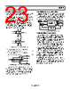
23 / 39 page  Data Sheet ADL5519 Rev. C | Page 23 of 39 DIFFERENCE OUTPUT—OUTP, OUTN The ADL5519 incorporates two operational amplifiers with rail-to- rail output capability to provide a channel difference output. As in the case of the output drivers for OUTA, OUTB, the output stages have the capability of driving greater than 10 mA. OUTA and OUTB are internally connected through 1 kΩ resistors to the inputs of each op amp. The VLVL pin is connected to the positive terminal of both op amps through 1 kΩ resistors to provide level shifting. The negative feedback terminal is also made available through a 1 kΩ resistor. The input impedance of VLVL is 1 kΩ, and the input impedance of FBKA, FBKB is 1 kΩ. See Figure 57 for the connections of these pins. OUTP VPSR VLVL FBKA COMR OUTA OUTB OUTN VPSR VLVL FBKB COMR OUTB OUTA 1kΩ 1kΩ 1kΩ 1kΩ 1kΩ 1kΩ 1kΩ 1kΩ Figure 57. OUTP, OUTN Interface Simplified Schematic If OUTP is connected to FBKA, OUTP is given as OUTP = OUTA − OUTB + VLVL (3) If OUTN is connected to FBKB, OUTN is given as OUTN = OUTB − OUTA + VLVL (4) OUTA FBKA FBKB OUTP OUTN OUTB 14 13 12 11 Figure 58. Op Amp Connections (All Resistors Are 1 kΩ ± 20%) In this configuration, all four measurements, OUTA, OUTB, OUTP, and OUTN, are available simultaneously. A differential output can be taken from OUTP − OUTN, and VLVL can be used to adjust the common-mode level for an ADC connection. This is convenient not only for driving a differential ADC but also for removing any temperature variation on VLVL. DESCRIPTION OF CHARACTERIZATION The general hardware configuration used for most of the ADL5519 characterization is shown in Figure 59. The signal sources used in this example are the E8251A from Agilent Technologies. The INHA, INHB input pins are driven by Agilent signal sources, and the output voltages are measured using a voltmeter. COMPUTER CONTROLLER AGILENT 34970A METER/ SWITCHING ADL5519 CHARACTERIZATION BOARD OUTA OUTB OUTP OUTN VREF TEMP INA INB –3dB SIGNAL SOURCE –3dB SIGNAL SOURCE Figure 59. General Characterization Configuration BASIS FOR ERROR CALCULATIONS The input power and output voltage are used to calculate the slope and intercept values. The slope and intercept are calculated using linear regression over the input range from −40 dBm to −10 dBm. The slope and intercept terms are used to generate an ideal line. The error is the difference in measured output voltage compared to the ideal output line. This is a measure of the linearity of the device. Refer to the Device Calibration section for more information on calculating slope, intercept, and error. Error from the linear response to the CW waveform is not a measure of absolute accuracy because it is calculated using the slope and intercept of each device. However, error verifies the linearity and the effects of modulation on device response. Similarly, at temperature extremes, error represents the output voltage variations from the 25°C ideal line performance. Data presented in the graphs is the typical error distribution observed during characterization of the ADL5519. Pulse response of the ADL5519 is 6 ns/8 ns rise/fall times. For the fastest response time, the capacitance on OUTA, OUTB should be kept to a minimum. Any capacitance on the output pins should be counterbalanced with an equal capacitance on the CLPA, CLPB pins to prevent ringing on the output. |
|
链接网址 |
| ALLDATASHEET是否为您带来帮助? [ DONATE ] |
关于 Alldatasheet | 广告服务 | 联系我们 | 隐私政策 | 数据表链接 | 链接交换 | 制造商名单 All Rights Reserved©Alldatasheet.com |
| Russian : Alldatasheetru.com | Korean : Alldatasheet.co.kr | Spanish : Alldatasheet.es | French : Alldatasheet.fr | Italian : Alldatasheetit.com Portuguese : Alldatasheetpt.com | Polish : Alldatasheet.pl | Vietnamese : Alldatasheet.vn Indian : Alldatasheet.in | Mexican : Alldatasheet.com.mx | British : Alldatasheet.co.uk | New Zealand : Alldatasheet.co.nz |
|
Family Site : ic2ic.com |
icmetro.com |
 Chinese ▼
 English
 Chinese
 German
 Japanese
 Russian
 Korean
 Spanish
 French
 Italian
 Portuguese
 Polish
 Vietnamese
 Indian
 Mexican
 British
 New Zealand