|
数据搜索系统,热门电子元器件搜索 |
|
|
数据搜索系统,热门电子元器件搜索 |
|
ADL5519ACPZ-R2 数据表(PDF) 24 Page - Analog Devices |
|
|
|||||||||||||||||||||||||||||
ADL5519ACPZ-R2 数据表(HTML) 24 Page - Analog Devices |
|
|
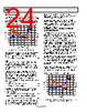
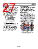
24 / 39 page  ADL5519 Data Sheet Rev. C | Page 24 of 39 DEVICE CALIBRATION The measured transfer function of the ADL5519 at 2.2 GHz is shown in Figure 60. The figure shows plots of both output voltage vs. input power and calculated error vs. input power. As the input power varies from −60 dBm to −5 dBm, the output voltage varies from 1.7 V to about 0.5 V. VOUT2 PIN1 PIN2 PIN (dBm) VOUT1 –60 –50 –40 –30 –20 0 10 –10 2.00 1.75 1.50 1.25 1.00 0.75 0.50 0.25 0 2.0 1.5 1.0 0.5 0 –0.5 –1.0 –1.5 –2.0 Figure 60. Transfer Function at 2.2 GHz with Calibration Points Because slope and intercept vary from device to device, board- level calibration must be performed to achieve the highest accuracy. The equation for output voltage can be written as VOUT = Slope × (PIN − Intercept) (6) where: Slope is the change in output voltage divided by the change in input power, PIN, expressed in decibels (dB). Intercept is the calculated power at which the output voltage would be 0 V. Note that an output voltage of 0 V can never be achieved. In general, calibration is performed by applying two known signal levels to the ADL5519 input and measuring the corre- sponding output voltages. The calibration points are generally chosen to be within the linear-in-dB operating range of the device (see the Specifications section for more details). Calculation of the slope and intercept is accomplished using the following equations: Slope = (VOUT1 − VOUT2)/(PIN1 − PIN2) (7) Intercept = PIN1 − (VOUT1/Slope) (8) Once slope and intercept are calculated, an equation can be written that calculates the input power based on the output voltage of the detector. PIN (Unknown) = (VOUT1(MEASURED)/Slope) + Intercept (9) The log conformance error of the calculated power is given by Error (dB) = (VOUT(MEASURED) − VOUT(IDEAL))/Slope (10) Figure 60 includes a plot of the error at 25°C, the temperature at which the log amp is calibrated. Note that the error is not 0 dB over the full dynamic range. This is because the log amp does not perfectly follow the ideal VOUT vs. PIN equation, even within its operating region. The error at the calibration points of −35 dBm and −11 dBm is equal to 0 dB, by definition. Figure 60 also shows error plots for the output voltage at −40°C and +85°C. These error plots are calculated using the slope and intercept at 25°C. This is consistent with calibration in a mass-production environment, where calibration over temperature is not practical. ADJUSTING ACCURACY THROUGH CHOICE OF CALIBRATION POINTS In some applications, very high accuracy is required at one power level or over a reduced input range. For example, in a wireless transmitter, the accuracy of the high power amplifier (HPA) is most critical at or close to full power. In applications like AGC control loops, good linearity and temperature performance are necessary over a large input power range. The temperature crossover point (the power level at which there is no drift in performance from −40°C to −80°C) can be shifted from high power levels to midpower levels using the method shown in the Temperature Compensation Adjustment section. This shift equalizes the temperature performance over the complete power range. The linearity of the transfer function can be equalized by changing the calibration points. Figure 61 demonstrates this equalization by changing the cali- bration points used in Figure 60 to −46 dBm and −22 dBm. This adjustment of the calibration points changes the linearity to greater than ±0.25 dB over a 50 dB dynamic range at the expense of a slight decrease in linearity at power levels between −40 dBm and −25 dBm. Calibration points should be chosen to suit the application at hand. In general, however, do not choose calibration points in the nonlinear portion of the log amp transfer function (greater than −10 dBm or less than −40 dBm, in this example). VOUT2 PIN1 PIN2 VOUT1 –60 –50 –40 –30 –20 0 10 –10 PIN (dBm) 2.00 1.75 1.50 1.25 1.00 0.75 0.50 0.25 0 2.0 1.5 1.0 0.5 0 –0.5 –1.0 –1.5 –2.0 Figure 61. Dynamic Range Extension by Choosing Calibration Points That Are Close to the End of the Linear Range, 2.14 GHz |
|
链接网址 |
| ALLDATASHEET是否为您带来帮助? [ DONATE ] |
关于 Alldatasheet | 广告服务 | 联系我们 | 隐私政策 | 数据表链接 | 链接交换 | 制造商名单 All Rights Reserved©Alldatasheet.com |
| Russian : Alldatasheetru.com | Korean : Alldatasheet.co.kr | Spanish : Alldatasheet.es | French : Alldatasheet.fr | Italian : Alldatasheetit.com Portuguese : Alldatasheetpt.com | Polish : Alldatasheet.pl | Vietnamese : Alldatasheet.vn Indian : Alldatasheet.in | Mexican : Alldatasheet.com.mx | British : Alldatasheet.co.uk | New Zealand : Alldatasheet.co.nz |
|
Family Site : ic2ic.com |
icmetro.com |
 Chinese ▼
 English
 Chinese
 German
 Japanese
 Russian
 Korean
 Spanish
 French
 Italian
 Portuguese
 Polish
 Vietnamese
 Indian
 Mexican
 British
 New Zealand