|
数据搜索系统,热门电子元器件搜索 |
|
|
数据搜索系统,热门电子元器件搜索 |
|
ADL5902ACPZ-R2 数据表(PDF) 26 Page - Analog Devices |
|
|
|||||||||||||||||||||||||||||
ADL5902ACPZ-R2 数据表(HTML) 26 Page - Analog Devices |
|
|
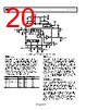
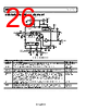
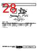
26 / 28 page  ADL5902 Data Sheet Rev. B | Page 26 of 28 EVALUATION BOARD SCHEMATICS AND ARTWORK X2 X2 BIAS AND POWER- DOWN CONTROL 1 NC NC NC LINEAR-IN-dB VGA (NEGATIVE SLOPE) IDET 26pF 2 3 4 11 10 9 5 6 7 8 16 15 14 13 ADL5902 12 VREF 2.3V TEMPERATURE SENSOR INLO INHI VPOS POS TEMP (BLACK) GND (BLACK) VSET (BLACK) VOUT (BLACK) VTGT (BLACK) VREF (BLACK) TEMP VSET VOUT CLPF COMM COMM VTGT VREF TADJ/PWDN G = 5 ITGT R3 60.4Ω C10 100pF C12 100pF VPOS +5V (RED) C4 100pF C3 0.1µF C5 100pF C7 0.1µF R11 2kΩ R10 3.74kΩ R12 301Ω R9 1430Ω C9 10µF RFIN R2 OPEN R6 0Ω R1 0Ω R15 OPEN TC2 PWDN (BLACK) Figure 54. Evaluation Board Schematic Table 8. Evaluation Board Configuration Options Component Function/Notes Default Value C10, C12, R3 RF input. The ADL5902 is generally driven single-ended. R3 is the input termination resistor and is chosen to give a 50 Ω input impedance over a broad frequency range. C10 = C12 = 100 pF R3 = 60.4 Ω R10, R11 VTGT interface. R10 and R11 are set up to provide 0.8 V to VTGT derived from VREF. R10 = 3.74 kΩ, R11 = 2 kΩ C4, C5, C7, C3 Power supply decoupling. The nominal supply decoupling consists of two pairs of 100 pF and 0.1 μF capacitors placed close to the two power supply pins of the ADL5902. C4 = C5 = 100 pF, C7 = C3 = 0.1 μF R1, R15, R2, R6 Output interface. In measurement mode, a portion of the voltage at the VOUT pin is fed back to the VSET pin via R6. Using the voltage divider created by R2 and R6, the magnitude of the slope of VOUT is increased by reducing the portion of VOUT that is fed back to VSET. In controller mode, R6 must be open. In this mode, the ADL5902 can control the gain of an external component. A setpoint voltage is applied to the VSET pin, the value of which corresponds to the desired RF input signal level applied to the ADL5902. R1 = R6= 0 Ω, R2 = R15 = open C9 Low-pass filter capacitors, CLPF. The low-pass filter capacitor provides the averaging for the ADL5902 rms computation. C9 = 0.1 μF R9, R12 TADJ/PWDN. The TADJ/PWDN pin controls the amount of nonlinear intercept temperature compensation and/or shuts down the device. The evaluation board is configured with TADJ connected to VREF through a resistor divider (R9, R12). R9 = 1430 Ω R12 = 301 Ω |
|
|
链接网址 |
| ALLDATASHEET是否为您带来帮助? [ DONATE ] |
关于 Alldatasheet | 广告服务 | 联系我们 | 隐私政策 | 数据表链接 | 链接交换 | 制造商名单 All Rights Reserved©Alldatasheet.com |
| Russian : Alldatasheetru.com | Korean : Alldatasheet.co.kr | Spanish : Alldatasheet.es | French : Alldatasheet.fr | Italian : Alldatasheetit.com Portuguese : Alldatasheetpt.com | Polish : Alldatasheet.pl | Vietnamese : Alldatasheet.vn Indian : Alldatasheet.in | Mexican : Alldatasheet.com.mx | British : Alldatasheet.co.uk | New Zealand : Alldatasheet.co.nz |
|
Family Site : ic2ic.com |
icmetro.com |
 Chinese ▼
 English
 Chinese
 German
 Japanese
 Russian
 Korean
 Spanish
 French
 Italian
 Portuguese
 Polish
 Vietnamese
 Indian
 Mexican
 British
 New Zealand