|
数据搜索系统,热门电子元器件搜索 |
|
|
数据搜索系统,热门电子元器件搜索 |
|
EV-RADAR-MMIC 数据表(PDF) 12 Page - Analog Devices |
|
|
|||||||||||||||||||||||||||||
EV-RADAR-MMIC 数据表(HTML) 12 Page - Analog Devices |
|
|
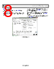
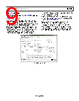
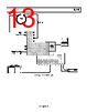
12 / 28 page  UG-866 EV-RADAR-MMIC2 User Guide Rev. B | Page 12 of 28 For another method to evaluate and test the performance of the ADF5901, ADF5904, and ADF4159, use the following procedure: 1. Install the EV-RADAR-MMIC evaluation software. 2. Connect the EV-ADAR-D2S evaluation board to the EV-RADAR-MMIC2 evaluation board. 3. Connect the SDP board to the EV-RADAR-MMIC2. 4. Connect the dc blocked TX_OUT2 (J9) connector to a delay cable or antenna. 5. Connect a delay cable or antenna to RX4_RFIN (J6) connector. 6. Run the EV-RADAR-MMIC software. 7. Select the SDP board and the EV-RADAR-MMIC2 (ADF5901, ADF5904, and ADF4159) device in the Select Device and Connection tab of the software window. 8. The software is set with default conditions for the following setup: a. Lock the ADF4159 to 12.0125 GHz (24.025 GHz on ADF5901). b. Calibrate the ADF5901 to 24.125 GHz. c. Generate a 5 ms, 200 MHz triangular ramp (24.025 GHz to 24.225 GHz). 9. In the ADF5904 Controls tab, click Initialize to power up the ADF5904. 10. In the ADF4159 Controls tab under the Main Controls section, click Write All Registers to power up the ADF4159. 11. In the ADF5901 Controls tab, click Initialize ADF5901 to power up and calibrate the ADF5901. See Figure 8 and Figure 9 for the typical setups. 12. In the ADF4159 Ramps and Shift Keying tab, enable the ramp and click Write R0 to enable the ramping of the ADF5901 Tx outputs. 13. Measure the baseband output signal on the O5 connector on the EV-ADAR-D2S board. |
|
|
链接网址 |
| ALLDATASHEET是否为您带来帮助? [ DONATE ] |
关于 Alldatasheet | 广告服务 | 联系我们 | 隐私政策 | 数据表链接 | 链接交换 | 制造商名单 All Rights Reserved©Alldatasheet.com |
| Russian : Alldatasheetru.com | Korean : Alldatasheet.co.kr | Spanish : Alldatasheet.es | French : Alldatasheet.fr | Italian : Alldatasheetit.com Portuguese : Alldatasheetpt.com | Polish : Alldatasheet.pl | Vietnamese : Alldatasheet.vn Indian : Alldatasheet.in | Mexican : Alldatasheet.com.mx | British : Alldatasheet.co.uk | New Zealand : Alldatasheet.co.nz |
|
Family Site : ic2ic.com |
icmetro.com |
 Chinese ▼
 English
 Chinese
 German
 Japanese
 Russian
 Korean
 Spanish
 French
 Italian
 Portuguese
 Polish
 Vietnamese
 Indian
 Mexican
 British
 New Zealand