|
数据搜索系统,热门电子元器件搜索 |
|
|
数据搜索系统,热门电子元器件搜索 |
|
STDRIVE102H 数据表(PDF) 38 Page - STMicroelectronics |
|
|
|||||||||||||||||||||||||||||
STDRIVE102H 数据表(HTML) 38 Page - STMicroelectronics |
|
|
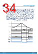
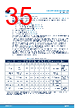
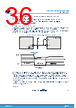
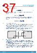
38 / 56 page  The typical sequence for the supplies is: • VDD UVLO is released (VDD > VDD(On)): the analog voltage on TCC/IGATE is now valid and the AFE is operative. The internal ADC can acquire the TCC/IGATE configuration, taking approximately 100 µs. • VCC UVLO is released (VCC > VCC(On)): the low-side drivers are operative. • Charge pump UVLO is released (VBOOT - VM > VCPump(On)): the high-side drivers are operative. Following the release of all the UVLO protections, the nFAULT pin is set high by the external pull-up resistor. 5.8 Standby and wake-up The standby pin is active low (nSTBY = 0: standby mode, nSTBY = 1: normal mode). The standby mode strongly reduces the current consumption down to ISTBY. The commutation to standby mode, which takes a tSTBY to be completed, follows a sequence of steps managed by the internal logic: 1. Before being disabled, all the drivers turn off the external MOSFETs. Then, the VGS of the external MOSFET is kept low by the internal 100 kΩ pull-down resistor, present on the GHSx/GLSx pins. 2. The AFE is disabled. 3. Both the linear regulators and the charge pump are switched off to reduce current consumption. 4. Open-drain pins are released. 5. The internal logic enters the standby state, and most of its circuitries are disabled. It is always preferable to force nSTBY = 0 before removing the main supply VS in the turn-off sequence of the device. When the nSTBY pin returns high, the device leaves the standby mode following the wake-up sequence: 1. Internal logic is initialized. 2. The linear regulators and the charge pump are turned on. 3. The AFE becomes active. The device can be considered operative as soon as its supplies (VCC, VDD, and VBOOT) are stable above the respective UVLO thresholds (nFAULT open-drain released). STDRIVE102BH, STDRIVE102H Device description DS14545 - Rev 1 page 38/56 |
|
链接网址 |
| ALLDATASHEET是否为您带来帮助? [ DONATE ] |
关于 Alldatasheet | 广告服务 | 联系我们 | 隐私政策 | 数据表链接 | 链接交换 | 制造商名单 All Rights Reserved©Alldatasheet.com |
| Russian : Alldatasheetru.com | Korean : Alldatasheet.co.kr | Spanish : Alldatasheet.es | French : Alldatasheet.fr | Italian : Alldatasheetit.com Portuguese : Alldatasheetpt.com | Polish : Alldatasheet.pl | Vietnamese : Alldatasheet.vn Indian : Alldatasheet.in | Mexican : Alldatasheet.com.mx | British : Alldatasheet.co.uk | New Zealand : Alldatasheet.co.nz |
|
Family Site : ic2ic.com |
icmetro.com |
 Chinese ▼
 English
 Chinese
 German
 Japanese
 Russian
 Korean
 Spanish
 French
 Italian
 Portuguese
 Polish
 Vietnamese
 Indian
 Mexican
 British
 New Zealand