|
数据搜索系统,热门电子元器件搜索 |
|
|
数据搜索系统,热门电子元器件搜索 |
|
CC2500-RTR1 数据表(PDF) 18 Page - Texas Instruments |
|
|
|||||||||||||||||||||||||||||
CC2500-RTR1 数据表(HTML) 18 Page - Texas Instruments |
|
|
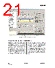
18 / 96 page  CC2500 SWRS040C Page 18 of 89 balun that converts the differential RF signal on CC2500 to a single-ended RF signal. C121 and C131 are needed for DC blocking. Together with an appropriate LC network, the balun components also transform the impedance to match a 50 antenna (or cable). Suggested values are listed in Table 15. The balun and LC filter component values and their placement are important to keep the performance optimized. It is highly recommended to follow the CC2500EM reference design ([4]). Crystal The crystal oscillator uses an external crystal with two loading capacitors (C81 and C101). See Section 26 on page 50 for details. Power Supply Decoupling The power supply must be properly decoupled close to the supply pins. Note that decoupling capacitors are not shown in the application circuit. The placement and the size of the decoupling capacitors are very important to achieve the optimum performance. The CC2500EM reference design ([4]) should be followed closely. Component Description C51 Decoupling capacitor for on-chip voltage regulator to digital part C81/C101 Crystal loading capacitors, see Section 26 on page 50 for details C121/C131 RF balun DC blocking capacitors C122/C132 RF balun/matching capacitors C123/C124 RF LC filter/matching capacitors L121/L131 RF balun/matching inductors (inexpensive multi-layer type) L122 RF LC filter inductor (inexpensive multi-layer type) R171 Resistor for internal bias current reference XTAL 26-27 MHz crystal, see Section 26 on page 50 for details Table 14: Overview of External Components (excluding supply decoupling capacitors) Antenna (50 Ohm) 1.8V-3.6V power supply 1 SCLK 2 SO (GDO1) 3 GDO2 4 DVDD 5 DCOUPL AVDD 15 AVDD 14 RF_N 13 RF_P 12 AVDD 11 XTAL C122 C132 L131 L121 L122 C123 C124 R171 C81 C101 C51 CSn GDO0 (optional) GDO2 (optional) SO (GDO1) SCLK SI CC2500 DIE ATTACH PAD: C131 C121 Alternative: Folded dipole PCB antenna (no external components needed) Figure 3: Typical Application and Evaluation Circuit (excluding supply decoupling capacitors) |
|
链接网址 |
| ALLDATASHEET是否为您带来帮助? [ DONATE ] |
关于 Alldatasheet | 广告服务 | 联系我们 | 隐私政策 | 数据表链接 | 链接交换 | 制造商名单 All Rights Reserved©Alldatasheet.com |
| Russian : Alldatasheetru.com | Korean : Alldatasheet.co.kr | Spanish : Alldatasheet.es | French : Alldatasheet.fr | Italian : Alldatasheetit.com Portuguese : Alldatasheetpt.com | Polish : Alldatasheet.pl | Vietnamese : Alldatasheet.vn Indian : Alldatasheet.in | Mexican : Alldatasheet.com.mx | British : Alldatasheet.co.uk | New Zealand : Alldatasheet.co.nz |
|
Family Site : ic2ic.com |
icmetro.com |
 Chinese ▼
 English
 Chinese
 German
 Japanese
 Russian
 Korean
 Spanish
 French
 Italian
 Portuguese
 Polish
 Vietnamese
 Indian
 Mexican
 British
 New Zealand