|
数据搜索系统,热门电子元器件搜索 |
|
|
数据搜索系统,热门电子元器件搜索 |
|
ADRF6806ACPZ-R7 数据表(PDF) 22 Page - Analog Devices |
|
|
|||||||||||||||||||||||||||||
ADRF6806ACPZ-R7 数据表(HTML) 22 Page - Analog Devices |
|
|
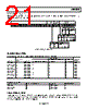
22 / 36 page  ADRF6806 Data Sheet Rev. B | Page 22 of 36 APPLICATIONS INFORMATION BASIC CONNECTIONS The basic circuit connections for a typical ADRF6806 application are shown in Figure 41. SUPPLY CONNECTIONS The ADRF6806 has several supply connections and on-board regulated reference voltages that should be bypassed to ground using low inductance bypass capacitors located in close proximity to the supply and reference pins of the ADRF6806. Specifically Pin 1, Pin 2, Pin 9, Pin 10, Pin 17, Pin 22, Pin 23, Pin 28, Pin 29, Pin 34, and Pin 40 should be bypassed to ground using individual bypass capacitors. Pin 40 is the decoupling pin for the on-board VCO LDO, and for best phase noise performance, several bypass capacitors ranging from 100 pF to 10 μF may help to improve phase noise performance. For additional details on bypassing the supply nodes, see the evaluation board schematic in Figure 43. SYNTHESIZER CONNECTIONS The ADRF6806 includes an on-board VCO and PLL for LO synthesis. An external reference must be applied for the PLL to operate. A 1 V p-p nominal external reference must be applied to Pin 6 through an ac coupling capacitor. The reference is compared to an internally divided version of the VCO output frequency to create a charge pump error current to control and lock the VCO. The charge pump output current is filtered and converted to a control voltage through the external loop filter that is then applied to the VTUNE pin (Pin 39). ADIsimPLL™ can be a helpful tool when designing the external charge pump loop filter. The typical Kv of the VCO, the charge pump output current magnitude, and PFD frequency should all be considered when designing the loop filter. The charge pump current magnitude can be set internally or with an external RSET resistor connected to Pin 5 and ground, along with the internal digital settings applied to the PLL (see the Register 4—Charge Pump, PFD, and Reference Path Control section for more details). 40 39 38 37 36 35 34 33 32 31 11 12 13 14 15 16 17 18 19 20 1 2 3 4 5 6 7 8 9 10 21 22 23 24 25 26 27 28 29 30 RFIN VOCM GND VCCBB GND GND RFIP GND VCCRF DECL3 MUXOUT GND RSET VCC1 GND CPOUT VCC2 REFIN VCC1 DECL2 ADRF6806 +3.3V +3.3V +5V RF INPUT +5V +3.3V EXTERNAL REFERENCE MONITOR OUTPUT R2 OPEN +3.3V SPI CONTROL BB Q-OUTPUT BALUN IF Q-OUTPUT RF INPUT BALUN BB I-OUTPUT BALUN IF I-OUTPUT CHARGE PUMP LOOP FILTER +1.65V +3.3V Figure 41. Basic Connections |
|
链接网址 |
| ALLDATASHEET是否为您带来帮助? [ DONATE ] |
关于 Alldatasheet | 广告服务 | 联系我们 | 隐私政策 | 数据表链接 | 链接交换 | 制造商名单 All Rights Reserved©Alldatasheet.com |
| Russian : Alldatasheetru.com | Korean : Alldatasheet.co.kr | Spanish : Alldatasheet.es | French : Alldatasheet.fr | Italian : Alldatasheetit.com Portuguese : Alldatasheetpt.com | Polish : Alldatasheet.pl | Vietnamese : Alldatasheet.vn Indian : Alldatasheet.in | Mexican : Alldatasheet.com.mx | British : Alldatasheet.co.uk | New Zealand : Alldatasheet.co.nz |
|
Family Site : ic2ic.com |
icmetro.com |
 Chinese ▼
 English
 Chinese
 German
 Japanese
 Russian
 Korean
 Spanish
 French
 Italian
 Portuguese
 Polish
 Vietnamese
 Indian
 Mexican
 British
 New Zealand