|
数据搜索系统,热门电子元器件搜索 |
|
|
数据搜索系统,热门电子元器件搜索 |
|
ADRF6806ACPZ-R7 数据表(PDF) 24 Page - Analog Devices |
|
|
|||||||||||||||||||||||||||||
ADRF6806ACPZ-R7 数据表(HTML) 24 Page - Analog Devices |
|
|
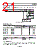
24 / 36 page  ADRF6806 Data Sheet Rev. B | Page 24 of 36 EVM MEASUREMENTS Figure 42 shows that the ADRF6806 exhibited excellent EVM performance, with the EVM being better than −40 dB over an RF input range of about +35 dB for a 4 QAM modulated signal at a 5 MHz symbol rate at a 0 Hz IF. The pulse shaping filter’s roll-off, or alpha, was set to 0.35. EVM and was tested for both power modes: lower power mode disabled (LPEN = 0) and low power mode enabled (LPEN = 1). When low power mode was enabled, the EVM was better at lower RF input signal levels due to less noise while running in low power mode. While in normal power mode (LPEN = 0), the EVM remained undegraded at higher RF input signal levels. EVM is a measure used to quantify the performance of a digital radio transmitter or receiver. A signal received by a receiver has all constellation points at their ideal locations; however, various imperfections in the implementation (such as magnitude imbalance, noise floor, and phase imbalance) cause the actual constellation points to deviate from their ideal locations. In general, a demodulator exhibits three distinct EVM limitations vs. received input signal power. As signal power increases, the distortion components increase. At large enough signal levels, where the distortion components due to the harmonic non- linearities in the device are falling in-band, EVM degrades as signal levels increase. At medium signal levels, where the demodulator behaves in a linear manner and the signal is well above any notable noise contributions, the EVM has a tendency to reach an optimal level determined dominantly by either quadrature accuracy and I/Q gain match of the demodulator or the precision of the test equipment. As signal levels decrease, such that the noise is a major contribution, the EVM performance vs. the signal level exhibits a decibel-for-decibel degradation with decreasing signal level. At lower signal levels, where noise proves to be the dominant limitation, the decibel EVM proves to be directly proportional to the SNR. –45 –40 –35 –30 –25 –20 –15 –10 –5 0 RF INPUT POWER (dBm) –60 –50 –40 –30 –20 –10 0 10 20 LPEN = 0 LPEN = 1 The basic test setup to test EVM for the ADRF6806 consisted of an Agilent E4438C, which was used as a signal source. The 140 MHz modulated signal was driven single-ended into the RFIN SMA connector of the ADRF6806 evaluation board. The IQ baseband outputs were taken differentially into a pair of AD8130 difference amplifiers to convert the differential signals to single-ended. The output impedance driven by the ADRF6806 was set to 450 Ω differential. The single-ended I and Q signals were then sampled by an Agilent DSO7104B oscilloscope. The Agilent 89600 VSA software was used to calculate the EVM of the signal. The signal source used for the reference input was a Wenzel 100 MHz quartz oscillator set to an amplitude of 1 V p-p. The reference path was set to divide-by-four, resulting in a PFD frequency of 25 MHz. Figure 42. EVM Measurements @ 140 MHz 16 QAM; Symbol Rate = 5 MHz; BB IF Frequency of 5 MHz |
|
链接网址 |
| ALLDATASHEET是否为您带来帮助? [ DONATE ] |
关于 Alldatasheet | 广告服务 | 联系我们 | 隐私政策 | 数据表链接 | 链接交换 | 制造商名单 All Rights Reserved©Alldatasheet.com |
| Russian : Alldatasheetru.com | Korean : Alldatasheet.co.kr | Spanish : Alldatasheet.es | French : Alldatasheet.fr | Italian : Alldatasheetit.com Portuguese : Alldatasheetpt.com | Polish : Alldatasheet.pl | Vietnamese : Alldatasheet.vn Indian : Alldatasheet.in | Mexican : Alldatasheet.com.mx | British : Alldatasheet.co.uk | New Zealand : Alldatasheet.co.nz |
|
Family Site : ic2ic.com |
icmetro.com |
 Chinese ▼
 English
 Chinese
 German
 Japanese
 Russian
 Korean
 Spanish
 French
 Italian
 Portuguese
 Polish
 Vietnamese
 Indian
 Mexican
 British
 New Zealand