|
数据搜索系统,热门电子元器件搜索 |
|
|
数据搜索系统,热门电子元器件搜索 |
|
M24C64-R 数据表(PDF) 14 Page - STMicroelectronics |
|
|
|||||||||||||||||||||||||||||
M24C64-R 数据表(HTML) 14 Page - STMicroelectronics |
|
|
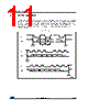
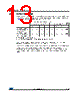
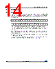
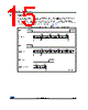
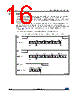
14 / 45 page  Instructions M24C64-W M24C64-R M24C64-F 14/45 DocID16891 Rev 30 5 Instructions 5.1 Write operations Following a Start condition the bus master sends a device select code with the R/W bit (RW) reset to 0. The device acknowledges this, as shown in Figure 9, and waits for two address bytes. The device responds to each address byte with an acknowledge bit, and then waits for the data byte. When the bus master generates a Stop condition immediately after a data byte Ack bit (in the “10th bit” time slot), either at the end of a Byte Write or a Page Write, the internal Write cycle tW is triggered. A Stop condition at any other time slot does not trigger the internal Write cycle. After the Stop condition and the successful completion of an internal Write cycle (tW), the device internal address counter is automatically incremented to point to the next byte after the last modified byte. During the internal Write cycle, Serial Data (SDA) is disabled internally, and the device does not respond to any requests. If the Write Control input (WC) is driven High, the Write instruction is not executed and the accompanying data bytes are not acknowledged, as shown in Figure 10. Table 3. Most significant address byte A15 A14 A13 A12 A11 A10 A9 A8 Table 4. Least significant address byte A7 A6 A5 A4 A3 A2 A1 A0 |
|
链接网址 |
| ALLDATASHEET是否为您带来帮助? [ DONATE ] |
关于 Alldatasheet | 广告服务 | 联系我们 | 隐私政策 | 数据表链接 | 链接交换 | 制造商名单 All Rights Reserved©Alldatasheet.com |
| Russian : Alldatasheetru.com | Korean : Alldatasheet.co.kr | Spanish : Alldatasheet.es | French : Alldatasheet.fr | Italian : Alldatasheetit.com Portuguese : Alldatasheetpt.com | Polish : Alldatasheet.pl | Vietnamese : Alldatasheet.vn Indian : Alldatasheet.in | Mexican : Alldatasheet.com.mx | British : Alldatasheet.co.uk | New Zealand : Alldatasheet.co.nz |
|
Family Site : ic2ic.com |
icmetro.com |
 Chinese ▼
 English
 Chinese
 German
 Japanese
 Russian
 Korean
 Spanish
 French
 Italian
 Portuguese
 Polish
 Vietnamese
 Indian
 Mexican
 British
 New Zealand