|
数据搜索系统,热门电子元器件搜索 |
|
|
数据搜索系统,热门电子元器件搜索 |
|
LTC1098AC 数据表(PDF) 13 Page - Linear Technology |
|
|
|||||||||||||||||||||||||||||
LTC1098AC 数据表(HTML) 13 Page - Linear Technology |
|
|
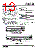
13 / 28 page  13 LTC1096/LTC1096L LTC1098/LTC1098L CLK tCYC CS B7* B6 B5 B4 B3 B2 B1 B0 B1 B2 B3 B4 B5 B6 B7 NULL BIT Hi-Z DOUT LTC1096/98 F01 POWER DOWN Hi-Z tsuCS tWAKEUP tCONV CLK CS tCYC POWER DOWN tWAKEUP B0 B1 B2 B3 B4 B5 B6 B7 Hi-Z DOUT tCONV HI-Z tsuCS NULL BIT *AFTER COMPLETING THE DATA TRANSFER, IF FURTHER CLOCKS ARE APPLIED WITH CS LOW, THE ADC WILL OUTPUT ZEROS INDEFINITELY. (MSB) (MSB) Figure 1. LTC1096(L) Operating Sequence S APPLICATI I FOR ATIO Power Down and Wake-Up Time The LTC1096(L)/LTC1098(L) draw power when the CS pin is low and shut themselves down when that pin is high. In order to have a correct conversion result, a 10 µs wake-up time must be provided from CS falling to the first falling clock (CLK) after the first rising CLK for the LTC1096(L) and from CS falling to the MSBF bit CLK falling for the LTC1098(L) (see Operating Sequence). If the LTC1096(L)/ LTC1098(L) are running with clock frequency less than or equal to 100kHz, the wake-up time is inherently provided. Example Two cases are shown at right to illustrate the relationship among wake-up time, setup time and CLK frequency for the LT1096(L). In Case 1 the clock frequency is 100kHz. One clock cycle is 10 µs which can be the wake-up time, while half of that can be the setup time. In Case 2 the clock frequency is 50kHz, half of the clock cycle plus the setup time (=1 µs) can be the wake-up time. If the CLK frequency is higher Case 1. Timing Diagram Case 2. Timing Diagram CS LTC1096/98 • AI Ex. CLK NULL BIT B7 tWAKEUP 10µs tsu tsu tWAKEUP DOUT CS CLK DOUT than 100kHz, Figure 1 shows the relationship between the wake-up time and setup time. The wake-up time is inherently provided for the LTC1098(L) with setup time = 1 µs (see Figure 2). |
|
|
链接网址 |
| ALLDATASHEET是否为您带来帮助? [ DONATE ] |
关于 Alldatasheet | 广告服务 | 联系我们 | 隐私政策 | 数据表链接 | 链接交换 | 制造商名单 All Rights Reserved©Alldatasheet.com |
| Russian : Alldatasheetru.com | Korean : Alldatasheet.co.kr | Spanish : Alldatasheet.es | French : Alldatasheet.fr | Italian : Alldatasheetit.com Portuguese : Alldatasheetpt.com | Polish : Alldatasheet.pl | Vietnamese : Alldatasheet.vn Indian : Alldatasheet.in | Mexican : Alldatasheet.com.mx | British : Alldatasheet.co.uk | New Zealand : Alldatasheet.co.nz |
|
Family Site : ic2ic.com |
icmetro.com |
 Chinese ▼
 English
 Chinese
 German
 Japanese
 Russian
 Korean
 Spanish
 French
 Italian
 Portuguese
 Polish
 Vietnamese
 Indian
 Mexican
 British
 New Zealand