|
数据搜索系统,热门电子元器件搜索 |
|
|
数据搜索系统,热门电子元器件搜索 |
|
AD8510ARM-R2 数据表(PDF) 14 Page - Analog Devices |
|
|
|||||||||||||||||||||||||||||
AD8510ARM-R2 数据表(HTML) 14 Page - Analog Devices |
|
|
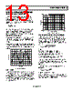
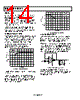
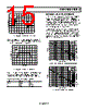
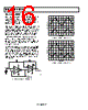
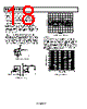
14 / 20 page  AD8510/AD8512/AD8513 Rev. E | Page 14 of 20 SETTLING TIME Settling time is the time it takes the output of the amplifier to reach and remain within a percentage of its final value after a pulse has been applied at the input. The AD8510/AD8512/ AD8513 settle to within 0.01% in less than 900 ns with a step of 0 V to 10 V in unity gain. This makes the each of the parts an excellent choice as a buffer at the output of DACs whose settling time is typically less than 1 µs. In addition to their fast settling time and fast slew rate, the AD8510/AD8512/AD8513’s low offset voltage drift and input offset current maintain full accuracy of 12-bit converters over the entire operating temperature range. OVERLOAD RECOVERY TIME Overload recovery, also known as overdrive recovery, is the time it takes the output of an amplifier to recover from a saturated condition to its linear region. This recovery time is particularly important in applications where the amplifier must amplify small signals in the presence of large transient voltages. Figure 43 shows the positive overload recovery of the AD8510/AD8512/AD8513. The output recovers in approximately 200 ns from a saturated condition. TIME (2 µs/DIV) 200mV 0V 0V –15V VSY = ±15V VIN = 200mV AV = –100 RL = 10kΩ Figure 43. Positive Overload Recovery The negative overdrive recovery time shown in Figure 44 is less than 200 ns. In addition to the fast recovery time, the AD8510/AD8512/ AD8513 show excellent symmetry of the positive and negative recovery times. This is an important feature for transient signal rectification, because the output signal is kept equally undis- torted throughout any given period. TIME (2 µs/DIV) –200mV 0V 0V +15V VSY = ±15V AV = –100 RL = 10kΩ Figure 44. Negative Overload Recovery CAPACITIVE LOAD DRIVE The AD8510/AD8512/AD8513 are unconditionally stable at all gains in inverting and noninverting configurations. They are capable of driving up to 1000 pF of capacitive loads without oscillation in unity gain, the worst-case configuration. However, as with most amplifiers, driving larger capacitive loads in a unity gain configuration may cause excessive overshoot and ringing or even oscillation. A simple snubber network reduces the amount of overshoot and ringing significantly. The advan- tage of this configuration is that the output swing of the ampli- fier is not reduced, because RS is outside the feedback loop. 7 4 6 AD8510 200mV RS CS CL VOUT V+ V– Figure 45. Snubber Network Configuration Figure 46 shows a scope photograph of the output of the AD8510/AD8512/AD8513 in response to a 400 mV pulse. The circuit is configured in positive unity gain (worst-case) with a load experience of 500 pF. |
|
|
链接网址 |
| ALLDATASHEET是否为您带来帮助? [ DONATE ] |
关于 Alldatasheet | 广告服务 | 联系我们 | 隐私政策 | 数据表链接 | 链接交换 | 制造商名单 All Rights Reserved©Alldatasheet.com |
| Russian : Alldatasheetru.com | Korean : Alldatasheet.co.kr | Spanish : Alldatasheet.es | French : Alldatasheet.fr | Italian : Alldatasheetit.com Portuguese : Alldatasheetpt.com | Polish : Alldatasheet.pl | Vietnamese : Alldatasheet.vn Indian : Alldatasheet.in | Mexican : Alldatasheet.com.mx | British : Alldatasheet.co.uk | New Zealand : Alldatasheet.co.nz |
|
Family Site : ic2ic.com |
icmetro.com |
 Chinese ▼
 English
 Chinese
 German
 Japanese
 Russian
 Korean
 Spanish
 French
 Italian
 Portuguese
 Polish
 Vietnamese
 Indian
 Mexican
 British
 New Zealand