|
数据搜索系统,热门电子元器件搜索 |
|
|
数据搜索系统,热门电子元器件搜索 |
|
AD8510ARM-R2 数据表(PDF) 18 Page - Analog Devices |
|
|
|||||||||||||||||||||||||||||
AD8510ARM-R2 数据表(HTML) 18 Page - Analog Devices |
|
|
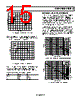
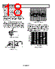
18 / 20 page  AD8510/AD8512/AD8513 Rev. E | Page 18 of 20 TIME (2ms/DIV) Signal Transmission Applications One popular signal transmission method uses pulse-width modulation. High data rates may require a fast comparator rather than an op amp. However, the need for sharp and undistorted signals may favor using a linear amplifier. The AD8510/AD8512/AD8513 make excellent voltage comparators. In addition to a high slew rate, the AD8510/ AD8512/AD8513 have a very fast saturation recovery time. In the absence of feedback, the amplifiers are in open-loop mode (very high gain). In this mode of operation, they spend much of their time in saturation. The circuit in Figure 54 compares two signals of different frequencies, namely a 100 Hz sine wave and a 1 kHz triangular wave. Figure 56 shows a scope photograph of the output wave- form. A pull-up resistor (typically 5 kΩ) may be connected from the output to VCC if the output voltage needs to reach the posi- tive rail. The trade-off is that power consumption will be higher. Figure 56. Pulse-Width Modulation Crosstalk Crosstalk, also known as channel separation, is a measure of signal feedthrough from one channel to the other on the same IC. The AD8512/AD8513 have a channel separation better than −90 dB for frequencies up to 10 kHz, and better than −50 dB for frequencies up to 10 MHz. Figure 57 shows the typical channel separation behavior between amplifier A (driving amplifier), with respect to amplifiers B, C, and D. VOUT V1 V2 4 2 6 7 3 –15V +15V FREQUENCY (Hz) 100 –160 10k –140 –120 –80 1k –60 –20 –40 100k 1M 10M –100 0 CH-D CH-C CH-B Figure 54. Pulse-Width Modulator VOUT 1 2 7 6 5 4 3 8 +VS 20k Ω 2.2k Ω 5k Ω 5k Ω –VS VIN 18V p-p CROSSTALK = 20 LOG VOUT 10VIN Figure 57. Channel Separation Figure 55. Crosstalk Test Circuit |
|
|
链接网址 |
| ALLDATASHEET是否为您带来帮助? [ DONATE ] |
关于 Alldatasheet | 广告服务 | 联系我们 | 隐私政策 | 数据表链接 | 链接交换 | 制造商名单 All Rights Reserved©Alldatasheet.com |
| Russian : Alldatasheetru.com | Korean : Alldatasheet.co.kr | Spanish : Alldatasheet.es | French : Alldatasheet.fr | Italian : Alldatasheetit.com Portuguese : Alldatasheetpt.com | Polish : Alldatasheet.pl | Vietnamese : Alldatasheet.vn Indian : Alldatasheet.in | Mexican : Alldatasheet.com.mx | British : Alldatasheet.co.uk | New Zealand : Alldatasheet.co.nz |
|
Family Site : ic2ic.com |
icmetro.com |
 Chinese ▼
 English
 Chinese
 German
 Japanese
 Russian
 Korean
 Spanish
 French
 Italian
 Portuguese
 Polish
 Vietnamese
 Indian
 Mexican
 British
 New Zealand