|
数据搜索系统,热门电子元器件搜索 |
|
|
数据搜索系统,热门电子元器件搜索 |
|
LED7708 数据表(PDF) 25 Page - STMicroelectronics |
|
|
|||||||||||||||||||||||||||||
LED7708 数据表(HTML) 25 Page - STMicroelectronics |
|
|
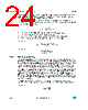
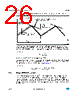
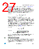
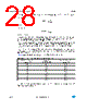
25 / 53 page  LED7708 Recommended operating conditions Doc ID 022698 Rev 1 25/53 In addition, when the FSW pin is tied to LDO3, the LED7708 uses a default 610 kHz fixed switching frequency, allowing the saving of a resistor in minimum component-count applications. The FSW pin can also be used as synchronization input, allowing the LED7708 to operate both as master or slave device. If a clock signal having a frequency within the capture range is applied to this pin, the device locks synchronized. The minimum pulse width which allows the synchronizing pulses to be detected is 270 ns (typ.). The SYNC pin is a synchronization output and provides a 35% (typ.) duty cycle clock when the LED7708 is set as master or a replica of the FSW pin when it is set as slave. It is used to connect multiple devices in a daisy chain configuration or to synchronize other switching converters running in the system with the LED7708. When an external synchronization clock is applied to the FSW pin, the internal oscillator is overdriven and the external power MOSFET is ignited on the rising edge of the synchronization signal while the slope compensation ramp starts on the falling edge of the same signal. For this reason, the duty cycle of the external synchronization clock should be 30% to 40% to prevent sub-harmonic instability when the boost converter is working in continuous-conduction mode (CCM). 8.3.3 Slope compensation The constant frequency, peak current-mode topology has the advantage of very easy loop compensation with output ceramic caps (reduced cost and size of the application) and fast transient response. In addition, the intrinsic peak current measurement simplifies the current limit protection, avoiding undesired saturation of the inductor. On the other side, this topology has a drawback: there is inherent open loop instability when operating with a duty cycle greater than 0.5. This phenomenon is known as “sub-harmonic instability” and can be avoided by adding an external ramp to the one coming from the sensed current. This compensating technique, based on the additional ramp, is called “slope compensation”. As seen in Figure 6, when the switching duty cycle is higher than 0.5, the small perturbation ΔIL dies away in subsequent cycles thanks to the slope compensation and the system reverts to a stable situation. |
|
链接网址 |
| ALLDATASHEET是否为您带来帮助? [ DONATE ] |
关于 Alldatasheet | 广告服务 | 联系我们 | 隐私政策 | 数据表链接 | 链接交换 | 制造商名单 All Rights Reserved©Alldatasheet.com |
| Russian : Alldatasheetru.com | Korean : Alldatasheet.co.kr | Spanish : Alldatasheet.es | French : Alldatasheet.fr | Italian : Alldatasheetit.com Portuguese : Alldatasheetpt.com | Polish : Alldatasheet.pl | Vietnamese : Alldatasheet.vn Indian : Alldatasheet.in | Mexican : Alldatasheet.com.mx | British : Alldatasheet.co.uk | New Zealand : Alldatasheet.co.nz |
|
Family Site : ic2ic.com |
icmetro.com |
 Chinese ▼
 English
 Chinese
 German
 Japanese
 Russian
 Korean
 Spanish
 French
 Italian
 Portuguese
 Polish
 Vietnamese
 Indian
 Mexican
 British
 New Zealand