|
数据搜索系统,热门电子元器件搜索 |
|
|
数据搜索系统,热门电子元器件搜索 |
|
M95010-R 数据表(PDF) 9 Page - STMicroelectronics |
|
|
|||||||||||||||||||||||||||||
M95010-R 数据表(HTML) 9 Page - STMicroelectronics |
|
|
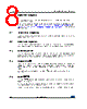
9 / 46 page  DocID6512 Rev 13 9/46 M950x0-W M950x0-R M950x0-DF Signal description 45 2.6 Write Protect (W) This input signal controls whether the memory is write protected. When Write Protect (W) is held low, writes to the memory are disabled, but other operations remain enabled. Write Protect (W) must either be driven high or low, but must not be left floating. 2.7 VSS ground VSS is the reference for the VCC supply voltage. 2.8 Supply voltage (VCC) 2.8.1 Operating supply voltage (VCC) Prior to selecting the memory and issuing instructions to it, a valid and stable VCC voltage within the specified [VCC(min), VCC(max)] range must be applied (see Table 9: Operating conditions (M950x0-W), Table 10: Operating conditions (M950x0-R) and Table 11: Operating conditions (M95040-DF, device grade 6)). This voltage must remain stable and valid until the end of the transmission of the instruction and, for a Write instruction, until the completion of the internal write cycle (tW). In order to secure a stable DC supply voltage, it is recommended to decouple the VCC line with a suitable capacitor (usually of the order of 10 nF to 100 nF) close to the VCC/VSS package pins. 2.8.2 Device reset In order to prevent inadvertent write operations during power-up, a power-on-reset (POR) circuit is included. At power-up, the device does not respond to any instruction until VCC reaches the internal reset threshold voltage (this threshold is defined in Table 9: Operating conditions (M950x0-W), Table 10: Operating conditions (M950x0-R) and Table 11: Operating conditions (M95040-DF, device grade 6) as VRES). When VCC passes over the POR threshold, the device is reset and is in the following state: • Standby Power mode • Deselected (note that, to be executed, an instruction must be preceded by a falling edge on Chip Select (S)) • Status register value: – Write Enable Latch (WEL) is reset to 0 – Write In Progress (WIP) is reset to 0 – SRWD, BP1 and BP0 bits remain unchanged (non-volatile bits) When the device is in the above state, it must not be accessed until VCC reaches a valid and stable VCC voltage within the specified [VCC(min), VCC(max)] range defined in Table 9: Operating conditions (M950x0-W), Table 10: Operating conditions (M950x0-R) and Table 11: Operating conditions (M95040-DF, device grade 6). |
|
链接网址 |
| ALLDATASHEET是否为您带来帮助? [ DONATE ] |
关于 Alldatasheet | 广告服务 | 联系我们 | 隐私政策 | 数据表链接 | 链接交换 | 制造商名单 All Rights Reserved©Alldatasheet.com |
| Russian : Alldatasheetru.com | Korean : Alldatasheet.co.kr | Spanish : Alldatasheet.es | French : Alldatasheet.fr | Italian : Alldatasheetit.com Portuguese : Alldatasheetpt.com | Polish : Alldatasheet.pl | Vietnamese : Alldatasheet.vn Indian : Alldatasheet.in | Mexican : Alldatasheet.com.mx | British : Alldatasheet.co.uk | New Zealand : Alldatasheet.co.nz |
|
Family Site : ic2ic.com |
icmetro.com |
 Chinese ▼
 English
 Chinese
 German
 Japanese
 Russian
 Korean
 Spanish
 French
 Italian
 Portuguese
 Polish
 Vietnamese
 Indian
 Mexican
 British
 New Zealand