|
数据搜索系统,热门电子元器件搜索 |
|
|
数据搜索系统,热门电子元器件搜索 |
|
M95010-R 数据表(PDF) 13 Page - STMicroelectronics |
|
|
|||||||||||||||||||||||||||||
M95010-R 数据表(HTML) 13 Page - STMicroelectronics |
|
|
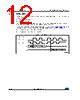
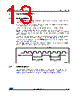
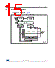
13 / 46 page  DocID6512 Rev 13 13/46 M950x0-W M950x0-R M950x0-DF Operating features 45 4 Operating features 4.1 Hold condition The Hold (HOLD) signal is used to pause any serial communications with the device without resetting the clocking sequence. During the Hold condition, the Serial Data Output (Q) is high impedance, and Serial Data Input (D) and Serial Clock (C) are Don’t Care. To enter the Hold condition, the device must be selected, with Chip Select (S) low. Normally, the device is kept selected, for the whole duration of the Hold condition. Deselecting the device while it is in the Hold condition has the effect of resetting the state of the device, and this mechanism can be used if it is required to reset any processes that had been in progress. The Hold condition starts when the Hold (HOLD) signal is driven low at the same time as Serial Clock (C) already being low (as shown in Figure 5: Hold condition activation). The Hold condition ends when the Hold (HOLD) signal is driven high at the same time as Serial Clock (C) already being low. Figure 5: Hold condition activation also shows what happens if the rising and falling edges are not timed to coincide with Serial Clock (C) being low. Figure 5. Hold condition activation 4.2 Status register Figure 6 shows the position of the Status register in the control logic of the device. This register contains a number of control bits and status bits, as shown in Table 6: Status register format and as detailed in Section 6.3: Read Status Register (RDSR). |
|
链接网址 |
| ALLDATASHEET是否为您带来帮助? [ DONATE ] |
关于 Alldatasheet | 广告服务 | 联系我们 | 隐私政策 | 数据表链接 | 链接交换 | 制造商名单 All Rights Reserved©Alldatasheet.com |
| Russian : Alldatasheetru.com | Korean : Alldatasheet.co.kr | Spanish : Alldatasheet.es | French : Alldatasheet.fr | Italian : Alldatasheetit.com Portuguese : Alldatasheetpt.com | Polish : Alldatasheet.pl | Vietnamese : Alldatasheet.vn Indian : Alldatasheet.in | Mexican : Alldatasheet.com.mx | British : Alldatasheet.co.uk | New Zealand : Alldatasheet.co.nz |
|
Family Site : ic2ic.com |
icmetro.com |
 Chinese ▼
 English
 Chinese
 German
 Japanese
 Russian
 Korean
 Spanish
 French
 Italian
 Portuguese
 Polish
 Vietnamese
 Indian
 Mexican
 British
 New Zealand