|
数据搜索系统,热门电子元器件搜索 |
|
|
数据搜索系统,热门电子元器件搜索 |
|
M95010-R 数据表(PDF) 11 Page - STMicroelectronics |
|
|
|||||||||||||||||||||||||||||
M95010-R 数据表(HTML) 11 Page - STMicroelectronics |
|
|
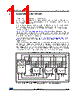
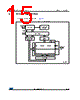
11 / 46 page  DocID6512 Rev 13 11/46 M950x0-W M950x0-R M950x0-DF Connecting to the SPI bus 45 3 Connecting to the SPI bus The device is fully compatible with the SPI protocol. All instructions, addresses and input data bytes are shifted in to the device, most significant bit first. The Serial Data Input (D) is sampled on the first rising edge of the Serial Clock (C) after Chip Select (S) goes low. All output data bytes are shifted out of the device, most significant bit first. The Serial Data Output (Q) is latched on the first falling edge of the Serial Clock (C) after the instruction (such as the Read from Memory Array and Read Status Register instructions) have been clocked into the device. Figure 3: Bus master and memory devices on the SPI bus shows an example of three memory devices connected to an MCU, on an SPI bus. Only one memory device is selected at a time, so only one memory device drives the Serial Data output (Q) line at a time, the other memory devices are high impedance. The pull-up resistor R (represented in Figure 3: Bus master and memory devices on the SPI bus) ensures that a device is not selected if the bus master leaves the S line in the high impedance state. In applications where the bus master might enter a state where all SPI bus inputs/outputs would be in high impedance at the same time (for example, if the bus master is reset during the transmission of an Instruction), the clock line (C) must be connected to an external pull- down resistor so that, if all inputs/outputs become high impedance, the C line is pulled low (while the S line is pulled high): this ensures that S and C do not become high at the same time, and so, that the tSHCH requirement is met. The typical value of R is 100 kΩ.. Figure 3. Bus master and memory devices on the SPI bus 1. The Write Protect (W) and Hold (HOLD) signals should be driven, high or low as appropriate. AI12304b Bus master SPI memory device SDO SDI SCK CQD S SPI memory device CQD S SPI mmory device CQD S CS3 CS2 CS1 SPI Interface with (CPOL, CPHA) = (0, 0) or (1, 1) W HOLD W HOLD W HOLD RR R VCC VCC VCC VCC VSS VSS VSS VSS R |
|
链接网址 |
| ALLDATASHEET是否为您带来帮助? [ DONATE ] |
关于 Alldatasheet | 广告服务 | 联系我们 | 隐私政策 | 数据表链接 | 链接交换 | 制造商名单 All Rights Reserved©Alldatasheet.com |
| Russian : Alldatasheetru.com | Korean : Alldatasheet.co.kr | Spanish : Alldatasheet.es | French : Alldatasheet.fr | Italian : Alldatasheetit.com Portuguese : Alldatasheetpt.com | Polish : Alldatasheet.pl | Vietnamese : Alldatasheet.vn Indian : Alldatasheet.in | Mexican : Alldatasheet.com.mx | British : Alldatasheet.co.uk | New Zealand : Alldatasheet.co.nz |
|
Family Site : ic2ic.com |
icmetro.com |
 Chinese ▼
 English
 Chinese
 German
 Japanese
 Russian
 Korean
 Spanish
 French
 Italian
 Portuguese
 Polish
 Vietnamese
 Indian
 Mexican
 British
 New Zealand