|
数据搜索系统,热门电子元器件搜索 |
|
|
数据搜索系统,热门电子元器件搜索 |
|
FS32K148UFT0VLHT 数据表(PDF) 4 Page - NXP Semiconductors |
|
|
|||||||||||||||||||||||||||||
FS32K148UFT0VLHT 数据表(HTML) 4 Page - NXP Semiconductors |
|
|
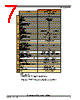
4 / 100 page  1 Block diagram Following figures show superset high level architecture block diagrams of S32K14x, S32K14xW and S32K11x series respectively. Other devices within the family have a subset of the features. See Feature comparison for chip specific values. Mux Trace port Crossbar switch (AXBS-Lite) eDMA DMA MUX Core Peripheral bus controller CRC WDOG S1 M0 M1 DSP NVIC ITM FPB DWT AWIC SWJ-DP TPIU JTAG & Serial Wire Arm Cortex M4F AHB-AP PPB M2 S2 GPIO Mux FPU Clock SPLL LPO 128 kHz Async 512B TCD LPIT LPI2C FlexIO Flash memory controller Code flash S0 Data flash Low Power Timer 12-bit ADC TRGMUX LPUART LPSPI FlexCAN FlexTimer PDB generation LPIT Peripherals present on all S32K devices Peripherals present on selected S32K devices Key: Device architectural IP on all S32K devices S3 FIRC 48 MHz M3 ENET SAI SOSC 8-40 MHz (see the "Feature Comparison" memory memory 4-40 MHz QuadSPI RTC CMP 8-bit DAC SIRC 8 MHz FlexRAM/ SRAM 1: On this device, NXP’s system MPU implements the safety mechanisms to prevent masters from accessing restricted memory regions. This system MPU provides memory protection at the level of the Crossbar Switch. Each Crossbar master (Core, DMA, Ethernet) can be assigned different access rights to each protected memory region. The Arm M4 core version in this family does not integrate the Arm Core MPU, which would concurrently monitor only core-initiated memory accesses. In this document, the term MPU refers to NXP’s system MPU. 2: For the device-specific sizes, see the "On-chip SRAM sizes" table in the "Memories and Memory Interfaces" chapter of the S32K1xx Series Reference Manual. section) ERM EWM MCM Lower region Upper region Main SRAM2 Code Cache EIM LMEM controller LMEM QSPI CSEc3 System MPU1 System MPU1 System MPU1 3: CSEc (Security) or EEPROM writes/erase will trigger error flags in HSRUN mode (112 MHz) because this use case is not allowed to execute simultaneously. The device need to switch to RUN mode (80 MHz) to execute CSEc (Security) or EEPROM writes/erase. Figure 1. High-level architecture diagram for the S32K14x and S32K14xW family Block diagram S32K1xx Data Sheet, Rev. 13, 04/2020 4 NXP Semiconductors |
|
链接网址 |
| ALLDATASHEET是否为您带来帮助? [ DONATE ] |
关于 Alldatasheet | 广告服务 | 联系我们 | 隐私政策 | 数据表链接 | 链接交换 | 制造商名单 All Rights Reserved©Alldatasheet.com |
| Russian : Alldatasheetru.com | Korean : Alldatasheet.co.kr | Spanish : Alldatasheet.es | French : Alldatasheet.fr | Italian : Alldatasheetit.com Portuguese : Alldatasheetpt.com | Polish : Alldatasheet.pl | Vietnamese : Alldatasheet.vn Indian : Alldatasheet.in | Mexican : Alldatasheet.com.mx | British : Alldatasheet.co.uk | New Zealand : Alldatasheet.co.nz |
|
Family Site : ic2ic.com |
icmetro.com |
 Chinese ▼
 English
 Chinese
 German
 Japanese
 Russian
 Korean
 Spanish
 French
 Italian
 Portuguese
 Polish
 Vietnamese
 Indian
 Mexican
 British
 New Zealand