|
数据搜索系统,热门电子元器件搜索 |
|
|
数据搜索系统,热门电子元器件搜索 |
|
ADRF6806ACPZ-R7 数据表(PDF) 23 Page - Analog Devices |
|
|
|||||||||||||||||||||||||||||
ADRF6806ACPZ-R7 数据表(HTML) 23 Page - Analog Devices |
|
|
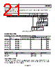
23 / 36 page  Data Sheet ADRF6806 Rev. B | Page 23 of 36 I/Q OUTPUT CONNECTIONS The ADRF6806 has I and Q baseband outputs. Each output stage consists of emitter follower output transistors with a low differential impedance of 28 Ω and can source up to 12 mA p-p differentially. A Mini-Circuits TCM9-1+ balun is used to trans- form a single-ended 50 Ω load impedance into a nominal 450 Ω differential impedance. RF INPUT CONNECTIONS The ADRF6806 uses a Mini-Circuits ADTL2-18+ balun with a 2:1 impedance ratio to transform a single-ended 50 Ω impedance into a differential 100 Ω impedance. Coupling capacitors whose impedance is small compared to 100 Ω at the frequency of operation are used to isolate the dc bias points of the RF input stage. CHARGE PUMP/VTUNE CONNECTIONS The ADRF6806 uses a loop filter to create the VTUNE voltage for the internal VCO. The loop filter in its simplest form is an integrating capacitor. It converts the current mode error signal coming out of the CPOUT pin into a voltage in which to control the VCO via the VTUNE voltage. The stock filter on the evaluation board has a bandwidth of 67 kHz. The loop filter contains five components, three capacitors, and two resistors. Changing the values of these components changes the bandwidth of the loop filter. LO SELECT INTERFACE The ADRF6806 has the option of either monitoring a scaled version of the internally generated LO (LOSEL pin driven high at 3.3 V) or providing an external LO source (LOSEL pin driven low to ground, the LDRV bit in Register 5 set low, and the LXL bit in Register 5 set high). See the Pin Configuration and Function Descriptions section for full operation details. EXTERNAL LO INTERFACE The ADRF6806 provides the option to use an external signal source for the LO into the IQ demodulating mixer core. It is important to note that the applied LO signal is divided down by a divider (programmable to between 4 and 80) prior to the actual IQ demodulating mixer core. The divider is determined by the register settings in the LO path and mixer control register (see the Register 5—LO Path and Demodulator Control section). The LO input pins (Pin 37 and Pin 38) present a broadband differential 50 Ω input impedance. The LOP and LON input pins must be ac-coupled. This is achieved on the evaluation board via a Mini-Circuits TC1-1-13+ balun with a 1:1 impedance ratio. When not in use, the LOP and LON pins can be left unconnected. SETTING THE FREQUENCY OF THE PLL The frequency of the VCO/PLL, once locked, is governed by the values programmed into the PLL registers, as follows: fPLL = fPFD × 2 × (INT + FRAC/MOD) where: fPLL is the frequency at the VCO when the loop is locked. fPFD is the frequency at the input of the phase frequency detector. INT is the integer divide ratio programmed into Register 0. MOD is the modulus divide ratio programmed into Register 1. FRAC is the fractional value programmed into Register 2. The practical lower limit of the reference input frequency is determined by the combination of the desired fPLL and the maximum programmable integer divide ratio of 119 and reference input frequency multiplier of 2. For a maximum fPLL of 4200 MHz, fREF > ~fPLL/(fPFD × 2 × 2), or 8.8 MHz. A lock detect signal is available as one of the selectable outputs through the MUXOUT pin, with logic high signifying that the loop is locked. REGISTER PROGRAMMING Because Register 6 controls the powering of the VCO and charge pump, it must be programmed once before programming the PLL frequency (Register 0, Register 1, and Register 2). The registers should be programmed starting with the highest register (Register 7) first and then sequentially down to Register 0 last. When Register 0, Register 1, or Register 2 is programmed, an internal VCO calibration is initiated that must execute when the other registers are set. Therefore, the order must be Register 7, Register 6, Register 5, Register 4, Register 3, Register 2, Register 1, and then Register 0. Whenever Register 0, Register 1, or Register 2 is written to, it initializes the VCO calibration (even if the value in these registers does not change). After the device has been powered up and the registers configured for the desired mode of operation, only Register 0, Register 1, or Register 2 must be programmed to change the LO frequency. If none of the register values is changing from their defaults, there is no need to program them. |
|
链接网址 |
| ALLDATASHEET是否为您带来帮助? [ DONATE ] |
关于 Alldatasheet | 广告服务 | 联系我们 | 隐私政策 | 数据表链接 | 链接交换 | 制造商名单 All Rights Reserved©Alldatasheet.com |
| Russian : Alldatasheetru.com | Korean : Alldatasheet.co.kr | Spanish : Alldatasheet.es | French : Alldatasheet.fr | Italian : Alldatasheetit.com Portuguese : Alldatasheetpt.com | Polish : Alldatasheet.pl | Vietnamese : Alldatasheet.vn Indian : Alldatasheet.in | Mexican : Alldatasheet.com.mx | British : Alldatasheet.co.uk | New Zealand : Alldatasheet.co.nz |
|
Family Site : ic2ic.com |
icmetro.com |
 Chinese ▼
 English
 Chinese
 German
 Japanese
 Russian
 Korean
 Spanish
 French
 Italian
 Portuguese
 Polish
 Vietnamese
 Indian
 Mexican
 British
 New Zealand