|
数据搜索系统,热门电子元器件搜索 |
|
|
数据搜索系统,热门电子元器件搜索 |
|
PIP3102-R 数据表(PDF) 2 Page - NXP Semiconductors |
|
|
|||||||||||||||||||||||||||||
PIP3102-R 数据表(HTML) 2 Page - NXP Semiconductors |
|
|
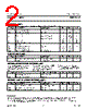
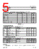
2 / 13 page  Philips Semiconductors Product Specification Logic level TOPFET PIP3102-R LIMITING VALUES Limiting values in accordance with the Absolute Maximum Rating System (IEC 134) SYMBOL PARAMETER CONDITIONS MIN. MAX. UNIT Continuous voltage V DS Drain source voltage 1 V IS = 0 V - 50 V Continuous currents I D Drain current V PS = 5 V; Tmb = 25˚C - self - A limited V PS = 0 V; Tmb = 85˚C - 30 A I I Input current -5 5 mA I F Flag current -5 5 mA I P Protection supply current -5 5 mA Thermal P tot Total power dissipation T mb = 25˚C - 90 W T stg Storage temperature -55 175 ˚C T j Junction temperature 2 continuous - 150 ˚C T sold Mounting base temperature during soldering - 260 ˚C ESD LIMITING VALUE SYMBOL PARAMETER CONDITIONS MIN. MAX. UNIT V C Electrostatic discharge capacitor Human body model; - 2 kV voltage C = 250 pF; R = 1.5 k Ω OVERLOAD PROTECTION LIMITING VALUE With an adequate protection supply For overload conditions an n-MOS The drain current is limited to connected, TOPFET can protect transistor turns on between the reduce dissipation in case of short itself from two types of overload - input and source to quickly circuit load. Refer to OVERLOAD overtemperature and short circuit discharge the power MOSFET CHARACTERISTICS. load. gate capacitance. SYMBOL PARAMETER REQUIRED CONDITION MIN. MAX. UNIT Overload protection 3 protection supply V DS Drain source voltage V PS ≥ 4 V 0 35 V OVERVOLTAGE CLAMPING LIMITING VALUES At a drain source voltage above 50 V the power MOSFET is actively turned on to clamp overvoltage transients. SYMBOL PARAMETER CONDITIONS MIN. MAX. UNIT Inductive load turn off I DM = 20 A; VDD ≤ 20 V E DSM Non-repetitive clamping energy T mb = 25˚C - 350 mJ E DRM Repetitive clamping energy T mb ≤ 95˚C; f = 250 Hz - 45 mJ 1 Prior to the onset of overvoltage clamping. For voltages above this value, safe operation is limited by the overvoltage clamping energy. 2 A higher T j is allowed as an overload condition but at the threshold Tj(TO) the over temperature trip operates to protect the switch. 3 All control logic and protection functions are disabled during conduction of the source drain diode. If the protection circuit was previously latched, it would be reset by this condition. October 2002 2 Rev 1.000 |
|
|
链接网址 |
| ALLDATASHEET是否为您带来帮助? [ DONATE ] |
关于 Alldatasheet | 广告服务 | 联系我们 | 隐私政策 | 数据表链接 | 链接交换 | 制造商名单 All Rights Reserved©Alldatasheet.com |
| Russian : Alldatasheetru.com | Korean : Alldatasheet.co.kr | Spanish : Alldatasheet.es | French : Alldatasheet.fr | Italian : Alldatasheetit.com Portuguese : Alldatasheetpt.com | Polish : Alldatasheet.pl | Vietnamese : Alldatasheet.vn Indian : Alldatasheet.in | Mexican : Alldatasheet.com.mx | British : Alldatasheet.co.uk | New Zealand : Alldatasheet.co.nz |
|
Family Site : ic2ic.com |
icmetro.com |
 Chinese ▼
 English
 Chinese
 German
 Japanese
 Russian
 Korean
 Spanish
 French
 Italian
 Portuguese
 Polish
 Vietnamese
 Indian
 Mexican
 British
 New Zealand