|
数据搜索系统,热门电子元器件搜索 |
|
|
数据搜索系统,热门电子元器件搜索 |
|
M24C02-R 数据表(PDF) 4 Page - STMicroelectronics |
|
|
|||||||||||||||||||||||||||||
M24C02-R 数据表(HTML) 4 Page - STMicroelectronics |
|
|
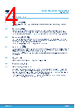
4 / 41 page  2 Signal description 2.1 Serial clock (SCL) The signal applied on the SCL input is used to strobe the data available on SDA(in) and to output the data on SDA(out). 2.2 Serial data (SDA) SDA is an input/output used to transfer data in or data out of the device. SDA(out) is an open drain output that may be wired-AND with other open drain or open collector signals on the bus. A pull-up resistor must be connected from serial data (SDA) to VCC (Figure 11 indicates how to calculate the value of the pull-up resistor). 2.3 Chip enable (E2, E1, E0) (E2,E1,E0) input signals are used to set the value that is to be looked for on the three least significant bits (b3, b2, b1) of the 7-bit device select code. These inputs must be tied to VCC or VSS, as shown in Table 2. When not connected (left floating), these inputs are read as low (0). For the UFDFPN5 package, the (E2,E1,E0) inputs are not connected. 2.4 Write control (WC) This input signal is useful for protecting the entire contents of the memory from inadvertent write operations. Write operations are disabled to the entire memory array when write control (WC) is driven high. Write operations are enabled when write control (WC) is either driven low or left floating. When write control (WC) is driven high, device select and address bytes are acknowledged, data bytes are not acknowledged. 2.5 VSS (ground) VSS is the reference for all signals, including the VCC supply voltage. 2.6 Supply voltage (VCC) 2.6.1 Operating supply voltage (VCC) Prior to selecting the memory and issuing instructions to it, a valid and stable VCC voltage within the specified [VCC(min), VCC(max)] range must be applied (see Operating conditions in Section 8 DC and AC parameters). In order to secure a stable DC supply voltage, it is recommended to decouple the VCC line with a suitable capacitor (usually of the order of 10 nF to 100 nF) close to the VCC/VSS package pins. This voltage must remain stable and valid until the end of the transmission of the instruction and, for a write instruction, until the completion of the internal write cycle (tW). M24C01/02-W M24C01/02-R M24C02-F Signal description DS9398 - Rev 7 page 4/41 |
|
链接网址 |
| ALLDATASHEET是否为您带来帮助? [ DONATE ] |
关于 Alldatasheet | 广告服务 | 联系我们 | 隐私政策 | 数据表链接 | 链接交换 | 制造商名单 All Rights Reserved©Alldatasheet.com |
| Russian : Alldatasheetru.com | Korean : Alldatasheet.co.kr | Spanish : Alldatasheet.es | French : Alldatasheet.fr | Italian : Alldatasheetit.com Portuguese : Alldatasheetpt.com | Polish : Alldatasheet.pl | Vietnamese : Alldatasheet.vn Indian : Alldatasheet.in | Mexican : Alldatasheet.com.mx | British : Alldatasheet.co.uk | New Zealand : Alldatasheet.co.nz |
|
Family Site : ic2ic.com |
icmetro.com |
 Chinese ▼
 English
 Chinese
 German
 Japanese
 Russian
 Korean
 Spanish
 French
 Italian
 Portuguese
 Polish
 Vietnamese
 Indian
 Mexican
 British
 New Zealand