|
数据搜索系统,热门电子元器件搜索 |
|
|
数据搜索系统,热门电子元器件搜索 |
|
ADBMS1818CSWAZ-R7 数据表(PDF) 39 Page - Analog Devices |
|
|
|||||||||||||||||||||||||||||
ADBMS1818CSWAZ-R7 数据表(HTML) 39 Page - Analog Devices |
|
|
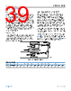
39 / 92 page  Data Sheet ADBMS1818 THEORY OF OPERATION analog.com Rev. B | 39 of 92 Thermal Shutdown To protect the ADBMS1818 from overheating, there is a thermal shutdown circuit included inside the IC. If the temperature detected on the die rises above approximately 150°C, the thermal shutdown circuit trips and resets the configuration register groups and S Control Register Group (including S control bits in PWM/S Control Register Group B) to their default states and turns off all discharge switches. When a thermal shutdown event has occurred, the THSD bit in Status Register Group B goes high. The CLRSTAT command can also set the THSD bit high for diagnostic purposes. This bit is cleared when a read operation is performed on Status Register Group B (RDSTATB command). The CLRSTAT command sets the THSD bit high for diagnostic purposes but does not reset the configuration register groups. Revision Code The Status Register Group B contains a 4-bit revision code (REV). If software detection of the device revision is necessary, contact the factory for details. Otherwise, ignore the code. In all cases, however, the values of all bits must be used when calculating the packet error code (PEC) on data reads. WATCHDOG AND DISCHARGE TIMER When there is no valid command for more than 2 seconds, the watchdog timer expires, which resets the configuration register bytes CFGAR0-3 and the GPIO bits in Configuration Register Group B in all cases. CFGAR4, CFGAR5, the S Control Register Group (including S control bits in PWM/S Control Register Group B) and the remainder of Configuration Register Group B are reset by the watchdog timer when the discharge timer is disabled. The WDT pin is pulled high by the external pull-up when the watchdog time elapses. The watchdog timer is always enabled, and the timer resets after every valid command with matching command PEC. The discharge timer is used to keep the discharge switches turned on for programmable time duration. If the discharge timer is being used, the discharge switches are not turned off when the watchdog timer is activated. To enable the discharge timer, connect the DTEN pin to VREG (see Figure 63). In this configuration, the discharge switches remain on for the programmed time duration that is determined by the DCTO value written in Configuration Register Group A. Table 33 shows the various time settings and the corresponding DCTO value. Figure 63. Watchdog and Discharge Timer Table 32. DCTO Settings DCTO 0 1 2 3 4 5 6 7 8 9 A B C D E F Time (Minutes) Disabled 0.5 1 2 3 4 5 10 15 20 30 40 60 75 90 120 |
|
链接网址 |
| ALLDATASHEET是否为您带来帮助? [ DONATE ] |
关于 Alldatasheet | 广告服务 | 联系我们 | 隐私政策 | 数据表链接 | 链接交换 | 制造商名单 All Rights Reserved©Alldatasheet.com |
| Russian : Alldatasheetru.com | Korean : Alldatasheet.co.kr | Spanish : Alldatasheet.es | French : Alldatasheet.fr | Italian : Alldatasheetit.com Portuguese : Alldatasheetpt.com | Polish : Alldatasheet.pl | Vietnamese : Alldatasheet.vn Indian : Alldatasheet.in | Mexican : Alldatasheet.com.mx | British : Alldatasheet.co.uk | New Zealand : Alldatasheet.co.nz |
|
Family Site : ic2ic.com |
icmetro.com |
 Chinese ▼
 English
 Chinese
 German
 Japanese
 Russian
 Korean
 Spanish
 French
 Italian
 Portuguese
 Polish
 Vietnamese
 Indian
 Mexican
 British
 New Zealand