|
数据搜索系统,热门电子元器件搜索 |
|
|
数据搜索系统,热门电子元器件搜索 |
|
STDRIVE102HTR 数据表(PDF) 25 Page - STMicroelectronics |
|
|
|||||||||||||||||||||||||||||
STDRIVE102HTR 数据表(HTML) 25 Page - STMicroelectronics |
|
|
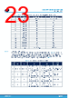
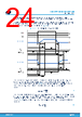
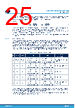
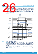
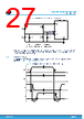
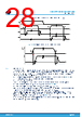
25 / 56 page  For a given couple of values of IGATE,on or IGATE,off a couple of tcc,on and tcc,off can be selected among the values of Table 10. In this case the total gate charge Qg,tot of the external MOSFET must be considered, in order to ensure the complete charge/discharge of the gate within the tcc time selected. Equation 3 tcc,on> QG,tot IGATE,on , tcc,off> QG,tot IGATE,off (3) The condition reported in Eq. (3) allows to completely turn off one MOSFET before turning on the complementary one, thus leading to the insertion of an adequate deadtime and preventing the risk of cross conduction. Since the IGATE,on is half of the IGATE,off, the relation reported in Eq. (3) brings to a tcc,on that is twice the tcc,off. For this reason, the STDRIVE102BH/H imposes this relation as shown in Table 10. Section 5.2.1.3 shows a practical example on how to select IGATE and TCC settings, based on what is described in this section. 5.2.1.2 Direct mode (INH/INL) In direct mode, each digital input is directly related to the state of each driver. The digital input INHx/INx (simply indicated as INHx) controls directly the high-side driver; the INLx/ENx (simply indicated as INLx) controls the low- side driver. High digital input implies the gate driver turns on the respective MOSFET; low digital input turns it off. The six digital inputs are managed as reported in Table 13, where x = 1, 2, 3 refers to the half-bridge driven. As shown in Table 13, whenever INHx and INLx are set high together, both drivers turn off their respective MOSFET. This logic configuration is referred to as interlocking and it is implemented to prevent both the power MOSFETs of the same half-bridge from turning on together, avoiding any dangerous cross-conduction. Table 13. Truth table for the direct mode EN INLx INHx GLSx GHSx OUTx Half-bridge status 0 Do not care Do not care All GLSx sink current All drivers’ status LOW All the low-side MOSFETs OFF All GHSx sink current All drivers’ status LOW All the high-side MOSFETs OFF All three phases are in high impedance 1 0 0 GLSx sink current Driver x status LOW Low-side MOSFET x OFF GHSx sink current Driver x status LOW High-side MOSFET x OFF OUTx in high impedance 1 0 1 GLSx sink current Driver x status LOW Low-side MOSFET x OFF GHSx source current Driver x status HIGH High-side MOSFET x ON OUTx at VM 1 1 0 GLSx source current Driver x status HIGH Low-side MOSFET x ON GHSx sink current Driver x status LOW High-side MOSFET x OFF OUTx at GND 1 1 1 GLSx sink current Driver x status LOW Low-side MOSFET x OFF GHSx sink current Driver x status LOW High-side MOSFET x OFF OUTx in high impedance Interlocking In direct mode, the driver timings are set to a fixed value tcc,on = 2240 ns and tcc,off = 1120 ns. These timings can ensure the complete charge or discharge of the gate for a wide range of external MOSFETs: referring to Equation 2, the maximum total gate charge supported by the drivers is 2240 nC. The deadtime between the turn-off of one driver and the turn-on of the complementary one is introduced by the user on the input signals INHx and INLx (Figure 15). STDRIVE102BH, STDRIVE102H Device description DS14545 - Rev 1 page 25/56 |
|
链接网址 |
| ALLDATASHEET是否为您带来帮助? [ DONATE ] |
关于 Alldatasheet | 广告服务 | 联系我们 | 隐私政策 | 数据表链接 | 链接交换 | 制造商名单 All Rights Reserved©Alldatasheet.com |
| Russian : Alldatasheetru.com | Korean : Alldatasheet.co.kr | Spanish : Alldatasheet.es | French : Alldatasheet.fr | Italian : Alldatasheetit.com Portuguese : Alldatasheetpt.com | Polish : Alldatasheet.pl | Vietnamese : Alldatasheet.vn Indian : Alldatasheet.in | Mexican : Alldatasheet.com.mx | British : Alldatasheet.co.uk | New Zealand : Alldatasheet.co.nz |
|
Family Site : ic2ic.com |
icmetro.com |
 Chinese ▼
 English
 Chinese
 German
 Japanese
 Russian
 Korean
 Spanish
 French
 Italian
 Portuguese
 Polish
 Vietnamese
 Indian
 Mexican
 British
 New Zealand