|
数据搜索系统,热门电子元器件搜索 |
|
|
数据搜索系统,热门电子元器件搜索 |
|
FT201XS-R 数据表(PDF) 25 Page - Future Technology Devices International Ltd. |
|
|
|||||||||||||||||||||||||||||
FT201XS-R 数据表(HTML) 25 Page - Future Technology Devices International Ltd. |
|
|
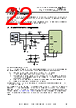
25 / 49 page  Copyright © 2014 Future Technology Devices International Limited 25 FT201X USB I2C SLAVE IC Datasheet Version 1.4 Document No.: FT_000627 Clearance No.: FTDI# 264 8 Application Examples The following sections illustrate possible applications of the FT201X. The illustrations have omitted pin numbers for ease of understanding since the pins differ between the FT201XS and FT201XQ package options. 8.1 USB to I2C Converter FT201X 1 2 3 4 5 SHIELD Ferrite Bead GND GND VCC GND VCC 3V3OUT USBDM USBDP VCCIO VCC RESET# 100nF 100nF 10nF 4.7uF + SDA SCL SCL SDA I2C MASTER DEVICE VCCIO 1k 1k 27R 27R GND 47pF 47pF Figure 8.1 Application Example showing USB to I2C Converter An example of using the FT201X as an I2C peripheral is shown in Figure 8.1. The FT201X is the slave on the I2C bus. Therefore the clock supplied to the SCL pin must come from the I2C Master. The device will support standard I2C data rates such as 100 kbit/s standard mode (SM), 400 kbit/s fast mode (FM), 1 Mbit/s Fast mode plus (FM+), and 3.4 Mbit/s High Speed mode (HS). The data line SDA is bi- directional. The master is initially in master transmit mode by sending a start bit followed by the 7-bit address of the slave it wishes to communicate with, which is finally followed by a single bit representing whether it wishes to write(0) to or read(1) from the slave. If the slave (FT201X) exists on the bus then it will respond with an ACK bit (active low for acknowledged) for that address. The master then continues in either transmit or receive mode (according to the read/write bit it sent), and the slave continues in its complementary mode (receive or transmit, respectively). The address and the data bytes are sent most significant bit first. The start bit is indicated by a high-to- low transition of SDA with SCL high; the stop bit is indicated by a low-to-high transition of SDA with SCL high. If the master wishes to write to the slave then it repeatedly sends a byte with the slave sending an ACK bit. (In this situation, the master is in master transmit mode and the slave is in slave receive mode.) If the master wishes to read from the slave then it repeatedly receives a byte from the slave, the master sending an ACK bit after every byte but the last one. (In this situation, the master is in master receive mode and the slave is in slave transmit mode.) The master then ends transmission with a stop bit, or it may send another START bit if it wishes to retain control of the bus for another transfer (a "combined message"). I²C defines three basic types of message, each of which begins with a START and ends with a STOP: Single message where a master writes data to a slave; |
|
链接网址 |
| ALLDATASHEET是否为您带来帮助? [ DONATE ] |
关于 Alldatasheet | 广告服务 | 联系我们 | 隐私政策 | 数据表链接 | 链接交换 | 制造商名单 All Rights Reserved©Alldatasheet.com |
| Russian : Alldatasheetru.com | Korean : Alldatasheet.co.kr | Spanish : Alldatasheet.es | French : Alldatasheet.fr | Italian : Alldatasheetit.com Portuguese : Alldatasheetpt.com | Polish : Alldatasheet.pl | Vietnamese : Alldatasheet.vn Indian : Alldatasheet.in | Mexican : Alldatasheet.com.mx | British : Alldatasheet.co.uk | New Zealand : Alldatasheet.co.nz |
|
Family Site : ic2ic.com |
icmetro.com |
 Chinese ▼
 English
 Chinese
 German
 Japanese
 Russian
 Korean
 Spanish
 French
 Italian
 Portuguese
 Polish
 Vietnamese
 Indian
 Mexican
 British
 New Zealand