|
数据搜索系统,热门电子元器件搜索 |
|
|
数据搜索系统,热门电子元器件搜索 |
|
FT201XS-R 数据表(PDF) 38 Page - Future Technology Devices International Ltd. |
|
|
|||||||||||||||||||||||||||||
FT201XS-R 数据表(HTML) 38 Page - Future Technology Devices International Ltd. |
|
|
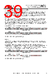
38 / 49 page  Copyright © 2014 Future Technology Devices International Limited 38 FT201X USB I2C SLAVE IC Datasheet Version 1.4 Document No.: FT_000627 Clearance No.: FTDI# 264 The User Memory Areas are highlighted in Green on the memory map. They can be read and written via both USB and I2C. All locations within this range are freely programmable; no areas have special functions and there is no checksum for the user area. Note that the application should take into account the specification for the number of write cycles in Section 6.4 if it will be writing to the MTP memory multiple times. Configuration Memory Area (writable) This area stores the configuration data for the device, including the data which is returned to the host in the configuration descriptors (e.g. the VID, PID and string descriptions) and also values which set the hardware configuration (the signal assigned to each CBUS pin for example). These values can have a significant effect on the behaviour of the device. Steps must be taken to ensure that these locations are not written to un-intentionally by an application which is intended to access only the user area. This area is included in a checksum which covers configuration areas of the memory, and so changing any value can also cause this checksum to fail. Configuration Memory Area (non-writable) This is a reserved area and the application should not write to this area of memory. Any attempt to write these locations will fail. 10.4 Hardware Requirements The hardware is the same as for a typical USB-I2C application and no additional hardware or programming voltages are required. The I2C connections are the same as shown in Section 8.1. For the USB connections, either a bus-powered configuration (see Section 7.1 and 7.3) or a self-powered configuration (see Section 7.2) could be used. 10.5 Protocol The I2C MTP memory protocol consists of 3 commands: Address MTP memory (0x10) Write MTP memory (0x12) Read MTP memory (0x14) For further details on the I2C protocol, refer to section 5. 10.5.1 Address MTP memory (0x10) This consists of a general call with a command phase followed by 2 data bytes which represent the MTP memory address allowing users to address, potentially, up to 64K byte addresses. 10.5.2 Write MTP memory (0x12) This consists of a general call with a command phase followed by 1 data byte which shall be programmed into the MTP memory at the address location set by the MTP memory address command. 10.5.3 Read MTP memory (0x14) This consists of a general call with a command phase followed by 1 data byte which is the data read from the MTP memory at the address location set by the MTP memory address command. |
|
链接网址 |
| ALLDATASHEET是否为您带来帮助? [ DONATE ] |
关于 Alldatasheet | 广告服务 | 联系我们 | 隐私政策 | 数据表链接 | 链接交换 | 制造商名单 All Rights Reserved©Alldatasheet.com |
| Russian : Alldatasheetru.com | Korean : Alldatasheet.co.kr | Spanish : Alldatasheet.es | French : Alldatasheet.fr | Italian : Alldatasheetit.com Portuguese : Alldatasheetpt.com | Polish : Alldatasheet.pl | Vietnamese : Alldatasheet.vn Indian : Alldatasheet.in | Mexican : Alldatasheet.com.mx | British : Alldatasheet.co.uk | New Zealand : Alldatasheet.co.nz |
|
Family Site : ic2ic.com |
icmetro.com |
 Chinese ▼
 English
 Chinese
 German
 Japanese
 Russian
 Korean
 Spanish
 French
 Italian
 Portuguese
 Polish
 Vietnamese
 Indian
 Mexican
 British
 New Zealand