|
数据搜索系统,热门电子元器件搜索 |
|
|
数据搜索系统,热门电子元器件搜索 |
|
AD8330ACP-R2 数据表(PDF) 15 Page - Analog Devices |
|
|
|||||||||||||||||||||||||||||
AD8330ACP-R2 数据表(HTML) 15 Page - Analog Devices |
|
|
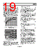
15 / 36 page  AD8330 Rev. D | Page 15 of 36 Normal Operating Conditions To minimize confusion, normal operating conditions are defined as follows: • The input pins are voltage driven (the source impedance is assumed to be zero). • The output pins are open circuited (the load impedance is assumed to be infinite). • Pin VMAG is unconnected setting up the output bias current (IN in the four-transistor gain cell) to its nominal value. • Pin CMGN is grounded. • MODE is either tied to a logic high or left unconnected, to set the up gain mode. The effects of other operating conditions are considered separately. Throughout this data sheet, the end-to-end voltage gain for the normal operating conditions is referred to as the basic gain. Under these conditions, it runs from 0 dB when VDBS = 0 V (where this voltage is more exactly measured with reference to Pin CMGN, which is not necessarily tied to ground) up to 50 dB for VDBS = 1.5 V. The gain does not fold over when the VDBS pin is driven below ground or above its nominal full- scale value. The input is accepted at the INHI/INLO differential port. These pins are internally biased to roughly the midpoint of the supply, VS (it is actually ~2.75 V for VS = 5 V, VDBS = 0 V, and 1.5 V for VS = 3 V), but the AD8330 is able to accept a forced common- mode value, from zero to VS, with certain limitations. This interface provides good common-mode rejection up to high frequencies (see Figure 16) and, thus, can be driven in either a single-sided or differential manner. However, operation using a differential drive is preferable, and this is assumed in the specifications, unless otherwise stated. The pin-to-pin input resistance is specified as 950 Ω ± 20%. The driving-point impedance of the signal source can range from zero up to values considerably in excess of this resistance, with a corresponding variation in noise figure (see Figure 53). In most cases, the input is coupled via two capacitors, chosen to provide adequate low frequency transmission. This results in the minimum input noise that increases when some other common-mode volt- age is forced onto these pins. The short-circuit, input-referred noise at maximum gain is approximately 5 nV/√Hz. Output Pin OPHI and Output Pin OPLO operate at a common- mode voltage at the midpoint of the supply, VS/2, within a few millivolts. This ensures that an analog-to-digital converter (ADC) attached to these outputs operates within the often narrow range permitted by their design. When a common- mode voltage other than VS/2 is required at this interface, it can easily be forced by applying an externally provided voltage to the output centering pin, CNTR. This voltage can run from zero to the full supply, though the use of such extreme values leaves only a small range for the differential output signal swing. The differential impedance measured between OPHI and OPLO is 150 Ω ± 20%. It follows that both the gain and the full-scale voltage swing depend on the load impedance; both are nominally halved when this is also 150 Ω. A fixed impedance output interface, rather than an op amp style voltage-mode output, is preferable in high speed applications because the effects of complex reactive loads on the gain and phase can be better controlled. The top end of the AD8330 ac response is optimally flat for a 12 pF load on each pin, but this is not critical, and the system remains stable for any value of load capacitance including zero. Another useful feature of this VGA in connection with the driving of an ADC is that the peak output magnitude can be precisely controlled by the voltage on Pin VMAG. Usually, this voltage is internally preset to 500 mV, and the peak differential unloaded output swing is ±2 V ± 3%. However, any voltage from zero to at least 5 V can be applied to this pin to alter the peak output in an exactly proportional way. Because either output pin can swing rail-to-rail, which in practice means down to at least 0.35 V and to within the same voltage below the supply, the peak-to-peak output between these pins can be as high as 10 V using VS = 6 V. INHI INLO VDBS VPSI COMM TRANSIMPEDANCE OUTPUT STAGE 500Ω 500Ω LINEAR-IN-dB INTERFACE MAGNITUDE INTERFACE 5kΩ ROUT = 150Ω 100µA VMAG VPSO OPHI OPLO ΔV = 0 12.65µA–4mA OR 4mA–12.65µA COMM VMAG MODE CNTR ΔV = 0 O/P CM-MODE NORMALLY AT VP/2 CM MODE FEEDBACK VDBS Figure 47. Schematic of Key Components Linear-in-dB Gain Control (VDBS) All Analog Devices, Inc., VGAs featuring a linear-in-dB gain law, such as the X-AMP® family, provide exact, constant gain scaling over the fully specified gain range, and the deviation from the ideal response is within a small fraction of a dB. For the AD8330, the scaling of both of its gain interfaces is substantially independent of process, supply voltage, or temperature. The basic gain, GB, is simply () mV 30 DBS B V dB G = (1) where VDBS is in volts. |
|
链接网址 |
| ALLDATASHEET是否为您带来帮助? [ DONATE ] |
关于 Alldatasheet | 广告服务 | 联系我们 | 隐私政策 | 数据表链接 | 链接交换 | 制造商名单 All Rights Reserved©Alldatasheet.com |
| Russian : Alldatasheetru.com | Korean : Alldatasheet.co.kr | Spanish : Alldatasheet.es | French : Alldatasheet.fr | Italian : Alldatasheetit.com Portuguese : Alldatasheetpt.com | Polish : Alldatasheet.pl | Vietnamese : Alldatasheet.vn Indian : Alldatasheet.in | Mexican : Alldatasheet.com.mx | British : Alldatasheet.co.uk | New Zealand : Alldatasheet.co.nz |
|
Family Site : ic2ic.com |
icmetro.com |
 Chinese ▼
 English
 Chinese
 German
 Japanese
 Russian
 Korean
 Spanish
 French
 Italian
 Portuguese
 Polish
 Vietnamese
 Indian
 Mexican
 British
 New Zealand