|
数据搜索系统,热门电子元器件搜索 |
|
|
数据搜索系统,热门电子元器件搜索 |
|
AD8330ACP-R2 数据表(PDF) 23 Page - Analog Devices |
|
|
|||||||||||||||||||||||||||||
AD8330ACP-R2 数据表(HTML) 23 Page - Analog Devices |
|
|
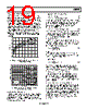
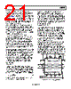
23 / 36 page  AD8330 Rev. D | Page 23 of 36 1.2 0 5ns 10ns 15ns 25ns 20ns 1.0 0.8 0.6 0.4 0.2 0 –0.2 0.2 –0.4 –0.6 –0.8 –1.0 –1.2 0 –0.2 1.2 1.0 0.8 0.6 0.4 0.2 0 –0.2 0.2 0 –0.2 –0.4 –0.6 –0.8 –1.0 –1.2 Figure 62. Typical Pulse Response for Figure 61 Figure 62 shows typical results for VDBS = 0.24 V, a square wave input amplitude of 450 mV (the actual combination is not important), a rise time of 2 ns, and VMAG raised to 2.0 V. In the upper waveforms, the load capacitors are both zero, and a small amount of overshoot is visible; with 40 pF, the response is cleaner. A shunt capacitance of 20 pF from OPHI to OPLO has a similar effect. Coupling capacitors for this demonstration are suffi- ciently large to prevent any visible droop over this time scale. The outputs at the load side eventually assume a mean value of zero, with negative and positive excursions depending on the duty cycle. The bandwidth from Pin VMAG to these outputs is somewhat higher than from the normal input pins. Thus, when this pin is used to rapidly modulate the primary signal, some further experimentation with response optimization may be required. In general, the AD8330 is very tolerant of a wide range of loading conditions. Preserving Absolute Gain Although the AD8330 is not laser trimmed, its absolute gain calibration, based mainly on ratios, is very good. Full details are found in the Specifications section and in the typical performance curves (see the Typical Performance Characteristics section). Nevertheless, having finite input and output impedances, the gain is necessarily dependent on the source and load conditions. The loss that is incurred when either of these is finite causes an error in the absolute gain. The absolute gain can also be uncertain due to the approximately ±20% tolerance in the absolute value of the input and output impedances. Often, such losses and uncertainties can be tolerated and accommodated by a correction to the gain control bias. On the other hand, the error in the loss can be essentially nulled by using appropriate modifications to either the source impedance (RS) or the load impedance (RL), or both (in some cases by padding them with series or shunt components). The formulation for this correction technique was previously described. However, to simplify its use, Table 5 shows spot values for combinations of RS and RL resulting in an overall loss that is not dependent on sample-to-sample variations in on chip resistances. Furthermore, this fixed and predictable loss can be corrected by an adjustment to VMAG , as indicated in Table 5. Table 5. Preserving Absolute Gain Uncorrected Loss RS (Ω) RL (Ω) Factor dB VMAG Required to Correct Loss 10 15 k 0.980 0.17 0.510 15 10 k 0.971 0.26 0.515 20 7.5 k 0.961 0.34 0.520 30 5.0 k 0.943 0.51 0.530 50 3.0 k 0.907 0.85 0.551 75 2.0 k 0.865 1.26 0.578 100 1.5 k 0.826 1.66 0.605 150 1.0 k 0.756 2.43 0.661 200 750 0.694 3.17 0.720 300 500 0.592 4.56 0.845 500 300 0.444 7.04 1.125 750 200 0.327 9.72 1.531 1 k 150 0.250 12.0 2.000 1.5 k 100 0.160 15.9 3.125 2 k 75 0.111 19.1 4.500 Calculation of Noise Figure The AD8330 noise is a consequence of its intrinsic voltage noise spectral density (ENSD) and the current noise spectral density (INSD). Their combined effect generates a net input noise, VNOISE_IN, that is a function of the input resistance of the device (RI), nominally 1 kΩ, and the differential source resistance (RS) as follows: ( { ) } 2 2 2 _ + + = S I NSD NSD IN NOISE R R I E V (16) Note that purely resistive source and input impedances as a conces- sion to simplicity is assumed. A more thorough treatment of noise mechanisms, for the case where the source is reactive, is beyond the scope of these brief notes. Also note that VNOISE_IN is the voltage noise spectral density appearing across INHI and INLO, the differential input pins. In preparing for the calculation of the noise figure, VSIG is defined as the open-circuit signal voltage across the source, and VIN is defined as the differential input to the AD8330. The relationship is simply () S I I SIG IN R R R V V + = (17) At maximum gain, ENSD is 4.1 nV/√Hz, and INSD is 3 pA/√Hz. Thus, the short-circuit voltage noise is ( ) () ( ) { }= + Ω + = 2 2 2 _ 0 k 1 Hz / pA 3 Hz / V n 1 . 4 IN NOISE V 5.08 nV/√Hz (18) Next, examine the net noise when RS = RI = 1 kΩ, often incor- rectly called the matching condition, rather than source impedance termination, which is the actual situation in this case. |
|
链接网址 |
| ALLDATASHEET是否为您带来帮助? [ DONATE ] |
关于 Alldatasheet | 广告服务 | 联系我们 | 隐私政策 | 数据表链接 | 链接交换 | 制造商名单 All Rights Reserved©Alldatasheet.com |
| Russian : Alldatasheetru.com | Korean : Alldatasheet.co.kr | Spanish : Alldatasheet.es | French : Alldatasheet.fr | Italian : Alldatasheetit.com Portuguese : Alldatasheetpt.com | Polish : Alldatasheet.pl | Vietnamese : Alldatasheet.vn Indian : Alldatasheet.in | Mexican : Alldatasheet.com.mx | British : Alldatasheet.co.uk | New Zealand : Alldatasheet.co.nz |
|
Family Site : ic2ic.com |
icmetro.com |
 Chinese ▼
 English
 Chinese
 German
 Japanese
 Russian
 Korean
 Spanish
 French
 Italian
 Portuguese
 Polish
 Vietnamese
 Indian
 Mexican
 British
 New Zealand