|
数据搜索系统,热门电子元器件搜索 |
|
|
数据搜索系统,热门电子元器件搜索 |
|
2-RK 数据表(PDF) 8 Page - TEKTRONIX, INC. |
|
|
|||||||||||||||||||||||||||||
2-RK 数据表(HTML) 8 Page - TEKTRONIX, INC. |
|
|
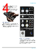
8 / 30 page  Mask testing Mask testing offers a good way to test the quality of a signal. A mask defines a portion of the oscilloscope display that a signal must not enter. A mask can be defined either based on a golden signal with user defined tolerances or drawing mask segments on the screen. 2 Series MSO provides a comprehensive set of mask tools that allow: • Defining test duration in number of waveforms • Setting a violation threshold that must be met before considering a test failure • Counting violations/failures and reporting statistical information • Setting actions upon violations, test failure, and test complete Limit mask test based on golden reference signal Serial protocol triggering and analysis (optional) The 2 Series MSO offers a robust set of tools for working with the most common serial buses found in embedded design including I2C, SPI, RS-232/422/485/UART, CAN, CAN FD, LIN, SENT. The protocol decode and triggering capability is invaluable to trace the flow of activity through a system by observing the traffic on one or more serial buses. • Serial protocol triggering lets you trigger on specific packet content including start of packet, specific addresses, specific data content, unique identifiers, and errors. • Bus waveforms provide a higher-level, combined view of the individual signals (for example clock, data, chip enable, etc.) that make up your bus, making it easy to identify where packets begin and end, and identifying sub-packet components such as address, data, identifier, CRC, and so on. • The bus waveform is time-aligned with all other displayed signals, making it easy to measure timing relationships across various parts of the system under test. • Bus decode table provides a tabular view of all decoded packets in an acquisition. Packets are time stamped and listed consecutively with columns for each component (address, data, and so on). Bus menu provides options to configure the bus parameters Digital channels (optional) The 2 Series MSO comes equipped with 16 digital channels. A P6316 digital probe can be used to connect up to 16 signals to the digital inputs of the oscilloscope. The accessories that are included with the probe enable you to connect directly to 8x2 square pin headers. The included flying lead sets and grabbers can be used to clip into surface mount devices or test points offering additional flexibility. Each digital channel can be viewed separately to see its state. Alternately, several digital channels can be grouped to view them together in a bus form. Symbol tables can also be applied to the bus view to get a higher level view of the bus transactions. Pattern triggering capability can be used to trigger on a pattern of interest. 2 Series MSO Datasheet www.tek.com 8 |
|
|
链接网址 |
| ALLDATASHEET是否为您带来帮助? [ DONATE ] |
关于 Alldatasheet | 广告服务 | 联系我们 | 隐私政策 | 数据表链接 | 链接交换 | 制造商名单 All Rights Reserved©Alldatasheet.com |
| Russian : Alldatasheetru.com | Korean : Alldatasheet.co.kr | Spanish : Alldatasheet.es | French : Alldatasheet.fr | Italian : Alldatasheetit.com Portuguese : Alldatasheetpt.com | Polish : Alldatasheet.pl | Vietnamese : Alldatasheet.vn Indian : Alldatasheet.in | Mexican : Alldatasheet.com.mx | British : Alldatasheet.co.uk | New Zealand : Alldatasheet.co.nz |
|
Family Site : ic2ic.com |
icmetro.com |
 Chinese ▼
 English
 Chinese
 German
 Japanese
 Russian
 Korean
 Spanish
 French
 Italian
 Portuguese
 Polish
 Vietnamese
 Indian
 Mexican
 British
 New Zealand