|
数据搜索系统,热门电子元器件搜索 |
|
|
数据搜索系统,热门电子元器件搜索 |
|
ADRF6602ACPZ-R7 数据表(PDF) 18 Page - Analog Devices |
|
|
|||||||||||||||||||||||||||||
ADRF6602ACPZ-R7 数据表(HTML) 18 Page - Analog Devices |
|
|
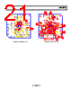
18 / 24 page  ADRF6602 Rev. 0 | Page 18 of 24 EVALUATION BOARD Figure 24 shows the schematic of the RoHS-compliant evalua- tion board for the ADRF6602. This board has four layers and was designed using Rogers 4350 hybrid material to minimize high frequency losses. FR4 material is also adequate if the design can accept the slightly higher trace loss of this material. The evaluation board is designed to operate using the internal VCO of the device (the default configuration) or with an external VCO. To use an external VCO, R62 and R12 should be removed. Place 0 Ω resistors in R63 and R11. The input of the external VCO should be connected to the VTUNE SMA connector, and the external VCO output should be connected to the LO IN/OUT SMA connector. In addition to these hard- ware changes, internal register settings must also be changed to enable operation with an external VCO (see the Register 6— VCO Control and VCO Enable (Default: 0x1E2106) section). Additional configuration options for the evaluation board are described in Table 9. EVALUATION BOARD CONTROL SOFTWARE Software to program the ADRF6602 is available for download from www.analog.com. To install the software, download and extract the zip file. Then run the following installation file: ADRF6x0x_3p0p0_XP_install.exe The evaluation board can be connected to the PC using a PC parallel port or a USB port. These options are selectable from the opening menu of the software interface (see Figure 22). The evaluation board is shipped with a 25-pin parallel port cable for connection to the PC parallel port. To connect the evaluation board to a USB port, a USB adapter board (Part No. EVAL-ADF4XXXZ-USB) must be purchased from www.analog.com. This board connects to the PC using a standard USB cable with USB mini-connector at one end. An additional 25-pin male to 9-pin female adapter is required to mate the ADF4XXXZ-USB board to the 9-pin D-Sub connector on the ADRF6602 evaluation board. Figure 22. Control Software Opening Menu Figure 23 shows the main menu of the control software with the default settings displayed. |
|
|
链接网址 |
| ALLDATASHEET是否为您带来帮助? [ DONATE ] |
关于 Alldatasheet | 广告服务 | 联系我们 | 隐私政策 | 数据表链接 | 链接交换 | 制造商名单 All Rights Reserved©Alldatasheet.com |
| Russian : Alldatasheetru.com | Korean : Alldatasheet.co.kr | Spanish : Alldatasheet.es | French : Alldatasheet.fr | Italian : Alldatasheetit.com Portuguese : Alldatasheetpt.com | Polish : Alldatasheet.pl | Vietnamese : Alldatasheet.vn Indian : Alldatasheet.in | Mexican : Alldatasheet.com.mx | British : Alldatasheet.co.uk | New Zealand : Alldatasheet.co.nz |
|
Family Site : ic2ic.com |
icmetro.com |
 Chinese ▼
 English
 Chinese
 German
 Japanese
 Russian
 Korean
 Spanish
 French
 Italian
 Portuguese
 Polish
 Vietnamese
 Indian
 Mexican
 British
 New Zealand