|
数据搜索系统,热门电子元器件搜索 |
|
|
数据搜索系统,热门电子元器件搜索 |
|
AD8366ACPZ-R7 数据表(PDF) 18 Page - Analog Devices |
|
|
|||||||||||||||||||||||||||||
AD8366ACPZ-R7 数据表(HTML) 18 Page - Analog Devices |
|
|
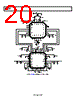
18 / 28 page  AD8366 Rev. A | Page 18 of 28 RF LO MATCHING NETWORK PAD FILTER BALUN LC LOW- PASS FILTER LC LOW- PASS FILTER LC LOW- PASS FILTER LC LOW- PASS FILTER ADL5523 ADL5380 AD8366 ADL5523 0 90 ADF4350 TO ADC Figure 51. Direct Conversion Receiver Block Diagram DIRECT CONVERSION RECEIVER DESIGN A direct conversion receiver directly demodulates an RF modulated carrier to baseband frequencies, where the signals can be detected and the conveyed information recovered. Eliminating the IF stages and directly converting the signal to effectively zero IF results in reduced component count. The image problems associated with the traditional superheterodyne architectures can be ignored as well. However, there are different challenges associated with direct conversion that include LO leakage, dc offsets, quadrature imperfections, and image rejection. LO leakage causes self mixing that results in squaring of the LO waveform which generates a dc offset that falls in band for the direct conversion receiver. Residual dc offsets create a similar interfering signal that falls in band. I/Q amplitude and phase mismatch lead to degraded SNR performance and poor image rejection in the direct conversion system. Figure 51 shows the block diagram for a direct conversion receiver system. QUADRATURE ERRORS AND IMAGE REJECTION An overall RF-to-baseband EVM performance was measured with the ADL5380 IQ demodulator preceding the AD8366, as shown in Figure 56. In this setup, no LC low-pass filters were used between the ADL5380 and AD8366. A 1900 MHz W-CDMA RF signal with a 3.84 MHz symbol rate was used. The local oscillator (LO) is set at 1900 MHz to obtain a zero IF baseband signal. The gain of the AD8366 is set to maximum gain (~20.25 dB). Figure 52 shows the SNR vs. the input power of the cascaded system for a 5 MHz analysis bandwidth. The broad input power range over which the system exhibits strong SNR performance reflects the superior dynamic range of the AD8366. 0 5 10 15 20 25 30 35 40 45 –75 –65 –55 –45 –35 –25 –15 –5 5 INPUT POWER (dBm) Figure 52. SNR vs. RF Input Power Level The image rejection ratio is the ratio of the intermediate frequency (IF) signal level produced by the desired input frequency to that produced by the image frequency. The image rejection ratio is expressed in decibels (dB). Appropriate image rejection is critical because the image power can be much higher than that of the desired signal, thereby plaguing the downconversion process. Amplitude and phase balance between the I/Q channels are critical for high levels of image rejection. Image rejection of greater than 47 dB was measured for the combined ADL5380 and the AD8366 for a 5 MHz baseband frequency, as seen in Figure 53. This level of image rejection corresponds to a ±0.5° phase mismatch and a ±0.05 dB of amplitude mismatch for the combined ADL5380 and AD8366. Looking back to Figure 7 and Figure 10, the AD8366 exhibits only ±0.05 dB of amplitude mismatch and ±0.05o of phase mismatch, thus implying that the AD8366 does not introduce additional amplitude and phase imbalance. 25 30 35 40 45 50 55 900 1500 1300 1100 1700 1900 2100 2300 2500 2700 2900 RF FREQUENCY (MHz) Figure 53. Image Rejection vs. RF Frequency |
|
|
链接网址 |
| ALLDATASHEET是否为您带来帮助? [ DONATE ] |
关于 Alldatasheet | 广告服务 | 联系我们 | 隐私政策 | 数据表链接 | 链接交换 | 制造商名单 All Rights Reserved©Alldatasheet.com |
| Russian : Alldatasheetru.com | Korean : Alldatasheet.co.kr | Spanish : Alldatasheet.es | French : Alldatasheet.fr | Italian : Alldatasheetit.com Portuguese : Alldatasheetpt.com | Polish : Alldatasheet.pl | Vietnamese : Alldatasheet.vn Indian : Alldatasheet.in | Mexican : Alldatasheet.com.mx | British : Alldatasheet.co.uk | New Zealand : Alldatasheet.co.nz |
|
Family Site : ic2ic.com |
icmetro.com |
 Chinese ▼
 English
 Chinese
 German
 Japanese
 Russian
 Korean
 Spanish
 French
 Italian
 Portuguese
 Polish
 Vietnamese
 Indian
 Mexican
 British
 New Zealand