|
数据搜索系统,热门电子元器件搜索 |
|
|
数据搜索系统,热门电子元器件搜索 |
|
LNBH25LS 数据表(PDF) 8 Page - STMicroelectronics |
|
|
|||||||||||||||||||||||||||||
LNBH25LS 数据表(HTML) 8 Page - STMicroelectronics |
|
|
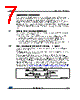
8 / 30 page  Application information LNBH25LS 8/30 DocID026753 Rev 3 2.3 Data encoding by external DiSEqC envelope control through the DSQIN pin If an external DiSEqC envelope source is available, it is possible to use the internal 22 kHz generator activated during the tone transmission by connecting the DiSEqC envelope source to the DSQIN pin. In this case the I²C tone control bits must be set: EXTM = 0 and TEN = 1. In this way, the internal 22 kHz signal is superimposed to the VOUT DC voltage to generate the LNB output 22 kHz tone. During the period in which the DSQIN is kept HIGH, the internal control circuit activates the 22 kHz tone output. The 22 kHz tone on the VOUT pin actives with about 6 µs delay from the DSQIN TTL signal rising edge, and it stops with a delay time in the range from 15 µs to 60 µs after the 22 kHz TTL signal on DSQIN has expired, refer to Figure 3: "Tone enable and disable timing (using envelope signal)". Figure 3: Tone enable and disable timing (using envelope signal) 2.4 Output current limit selection The linear regulator current limit threshold can be set by an external resistor connected to the ISEL pin. The resistor value defines the output current limit by the equation: where RSEL is the resistor connected between ISEL and GND expressed in kΩ and ILIM(typ.) is the typical current limit threshold expressed in mA. ILIM can be set up to 750 mA. 2.5 Output voltage selection The linear regulator output voltage level can be easily programmed in order to accomplish application specific requirements, using 4 bits of an internal data 1 register, see Section 7.3: "Data registers" and Table 13: "Output voltage selection table (data1 register, write mode)" for exact programmable values. Register writing is accessible via the I²C bus. 2.6 Diagnostic and protection functions The LNBH25LS has 3 diagnostic internal functions provided by I²C bus, by reading 3 bits on the status 1 register (in read mode). All the diagnostic bits are, in normal operation (that is no failure detected), set to LOW. Two diagnostic bits are dedicated to the overtemperature and overload protection status (OTF and OLF). One bit is dedicated to the input voltage (PNG) function. Once OLF (or OTF or PNG) bit has been activated (set to “1”), it is latched to “1” until relevant cause is removed and a new register reading operation is done. |
|
|
链接网址 |
| ALLDATASHEET是否为您带来帮助? [ DONATE ] |
关于 Alldatasheet | 广告服务 | 联系我们 | 隐私政策 | 数据表链接 | 链接交换 | 制造商名单 All Rights Reserved©Alldatasheet.com |
| Russian : Alldatasheetru.com | Korean : Alldatasheet.co.kr | Spanish : Alldatasheet.es | French : Alldatasheet.fr | Italian : Alldatasheetit.com Portuguese : Alldatasheetpt.com | Polish : Alldatasheet.pl | Vietnamese : Alldatasheet.vn Indian : Alldatasheet.in | Mexican : Alldatasheet.com.mx | British : Alldatasheet.co.uk | New Zealand : Alldatasheet.co.nz |
|
Family Site : ic2ic.com |
icmetro.com |
 Chinese ▼
 English
 Chinese
 German
 Japanese
 Russian
 Korean
 Spanish
 French
 Italian
 Portuguese
 Polish
 Vietnamese
 Indian
 Mexican
 British
 New Zealand