|
数据搜索系统,热门电子元器件搜索 |
|
|
数据搜索系统,热门电子元器件搜索 |
|
LNBH25LS 数据表(PDF) 19 Page - STMicroelectronics |
|
|
|||||||||||||||||||||||||||||
LNBH25LS 数据表(HTML) 19 Page - STMicroelectronics |
|
|
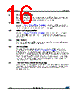
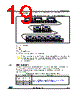
19 / 30 page  LNBH25LS I²C interface protocol DocID026753 Rev 3 19/30 The transmission is terminated when the master sets the acknowledge high with the following stop bit Figure 11: Example of reading procedure starting with first status address 0X0 ACK = acknowledge S = start P = stop R/W = 1/0, read/write bit X = 0/1, set the values to select the chip address. The writing procedure can start from any register address (status 1, 2 or data 1..4) by simply setting X values in the register address byte (after the chip address). It can be also stopped by the master by sending a stop condition after any acknowledge bit. 7.3 Data registers The data 1..4 registers can be addressed both in write and read mode. In read mode they return the last writing byte status received in the previous write transmission. The following tables provide the register address values of data 1..4 and a function description of each bit. Table 6: Data 1 (read/write register. Register address = 0X2) Bit Name Value Description Bit 0 (LSB) VSEL1 0/1 Output voltage selection bits. See Table 13: "Output voltage selection table (data1 register, write mode)" Bit 1 VSEL2 0/1 Bit 2 VSEL3 0/1 Bit 3 VSEL4 0/1 |
|
|
链接网址 |
| ALLDATASHEET是否为您带来帮助? [ DONATE ] |
关于 Alldatasheet | 广告服务 | 联系我们 | 隐私政策 | 数据表链接 | 链接交换 | 制造商名单 All Rights Reserved©Alldatasheet.com |
| Russian : Alldatasheetru.com | Korean : Alldatasheet.co.kr | Spanish : Alldatasheet.es | French : Alldatasheet.fr | Italian : Alldatasheetit.com Portuguese : Alldatasheetpt.com | Polish : Alldatasheet.pl | Vietnamese : Alldatasheet.vn Indian : Alldatasheet.in | Mexican : Alldatasheet.com.mx | British : Alldatasheet.co.uk | New Zealand : Alldatasheet.co.nz |
|
Family Site : ic2ic.com |
icmetro.com |
 Chinese ▼
 English
 Chinese
 German
 Japanese
 Russian
 Korean
 Spanish
 French
 Italian
 Portuguese
 Polish
 Vietnamese
 Indian
 Mexican
 British
 New Zealand