|
数据搜索系统,热门电子元器件搜索 |
|
|
数据搜索系统,热门电子元器件搜索 |
|
HCV1707R1-R48-R 数据表(PDF) 35 Page - Vicor Corporation |
|
|
|||||||||||||||||||||||||||||
HCV1707R1-R48-R 数据表(HTML) 35 Page - Vicor Corporation |
|
|
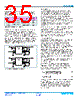
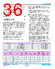
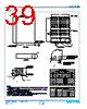
35 / 41 page  Cool-Power® ZVS Switching Regulators Rev 1.5 Page 35 of 41 03/2018 PI352x-00 Inductor Pairing The PI352x-00 utilizes an external inductor. This inductor has been optimized for maximum efficiency performance. Table 3 details the specific inductor value and part number utilized for each PI352x-00. The same inductor model may have different effective thermal impedances, depending on the model ZVS Buck paired with it. The thermal impedances are used in a virtual model of the inductor to estimate the maximum temperature, and the location of the maximum temperature may vary depending on the ZVS Buck model that the inductor is used with. This is because the effective thermal impedances are not only based on the geometry and materials used in the inductor, but include how the inductor power dissipation is distributed among core losses, DC copper losses, and AC copper losses. This distribution is dependent on the ZVS buck model that uses the inductor. Parallel Operation Multiple PI352x-00 can be connected in parallel to increase the output capability of a single output rail. When connecting modules in parallel, each EAO, TRK, and EN pin should be connected together. EAIN pins should remain separated, each with an REA1 and REA2, to reject noise differences between different modules' SGND pins. Current sharing will occur automatically in this manner so long as each inductor is the same value. Refer to the Electrical Characteristics table for maximum array size and array rated output current. Current sharing may be considered independent of synchronization and/or interleaving. Modules do not have to be interleaved or synchronized to share current. Due to the high output current capability of a single module and Critical Conduction Mode (CrCM) occurring at approximately 50% rated load, interleaving is not supported. Use of the PI352x-00 SYNCI pin is practical only under a limited set of conditions. Synchronizing to another converter or to a fixed external clock source can result in a significant reduction in output power capability or higher than expected ripple. Filter Considerations The PI352x-00 requires low impedance ceramic input capacitors (X7R/X5R or equivalent) to ensure proper start up and high frequency decoupling for the power stage. The PI352x-00 will draw nearly all of the high frequency current from the low impedance ceramic capacitors when the main high side MOSFET(s) are conducting. During the time the MOSFET(s) are off, the input capacitors are replenished from the source. Table 6 shows the recommended input and output capacitors to be used for the PI352x-00 as well as per capacitor RMS ripple current and the input and output ripple voltages. Table 5 lists the recommended input and output ceramic capacitors manufacturer and part numbers. It is very important to verify that the voltage supply source as well as the interconnecting lines are stable and do not oscillate. Input Filter Case 1 — Inductive source and local, external, input decoupling capacitance with negligible ESR (i.e., ceramic type): The voltage source impedance can be modeled as a series Rline Lline circuit. The high performance ceramic decoupling capacitors will not significantly damp the network because of their low ESR; therefore in order to guarantee stability the following conditions must be verified: Where rEQ_IN can be calculated by dividing the lowest line voltage by the full load input current. It is critical that the line source impedance be at least an octave lower than the converter’s dynamic input resistance, Equation 6. However, Rline cannot be made arbitrarily low otherwise Equation 5 is violated and the system will show instability, due to an under-damped RLC input network. Figure 96 — PI352x-00 parallel operation ZVS-Buck #1 VINVS1 VOUT VSP VSN VDIFF EAIN EAO COMP TRK PGND VDR SYNCO SYNCI PWRGD EN TESTx SGND CIN_1 COUT_1 REA2_1 L1_1 REA1_1 CCOMP_1 VIN EN ZVS-Buck #2 VINVS1 VOUT VSP VSN VDIFF EAIN EAO COMP TRK PGND VDR SYNCO SYNCI PWRGD EN TESTx SGND CIN_2 COUT_2 L1_2 CCOMP_2 VIN EN VOUT VOUT TRK EAO TRK EAO REA2_2 REA1_2 ( ) L line C IN_INT + CIN_EXT • r EQ_IN R line > (5) (6) R line << rEQ_IN Table 4 — PI352x-00 Inductor pairing Product System Value (nH) MFR Part Number Max Operating Temp (°C) PI3523 230 Eaton FP2207R1-R230-R 125 PI3525 230 Eaton FP2207R1-R230-R 125 PI3526 480 Eaton HCV1707R1-R48-R 125 |
|
链接网址 |
| ALLDATASHEET是否为您带来帮助? [ DONATE ] |
关于 Alldatasheet | 广告服务 | 联系我们 | 隐私政策 | 数据表链接 | 链接交换 | 制造商名单 All Rights Reserved©Alldatasheet.com |
| Russian : Alldatasheetru.com | Korean : Alldatasheet.co.kr | Spanish : Alldatasheet.es | French : Alldatasheet.fr | Italian : Alldatasheetit.com Portuguese : Alldatasheetpt.com | Polish : Alldatasheet.pl | Vietnamese : Alldatasheet.vn Indian : Alldatasheet.in | Mexican : Alldatasheet.com.mx | British : Alldatasheet.co.uk | New Zealand : Alldatasheet.co.nz |
|
Family Site : ic2ic.com |
icmetro.com |
 Chinese ▼
 English
 Chinese
 German
 Japanese
 Russian
 Korean
 Spanish
 French
 Italian
 Portuguese
 Polish
 Vietnamese
 Indian
 Mexican
 British
 New Zealand