|
数据搜索系统,热门电子元器件搜索 |
|
|
数据搜索系统,热门电子元器件搜索 |
|
HCV1707R1-R48-R 数据表(PDF) 36 Page - Vicor Corporation |
|
|
|||||||||||||||||||||||||||||
HCV1707R1-R48-R 数据表(HTML) 36 Page - Vicor Corporation |
|
|
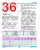
36 / 41 page  Cool-Power® ZVS Switching Regulators Rev 1.5 Page 36 of 41 03/2018 PI352x-00 Input Filter case 2 — Inductive source and local, external input decoupling capacitance with significant RC IN_EXT ESR (i.e., electrolytic type): In order to simplify the analysis in this case, the voltage source impedance can be modeled as a simple inductor Lline. Notice that the high performance ceramic capacitors CIN_INT within the PI352x-00 should be included in the external electrolytic capacitance value for this purpose. The stability criteria will be: Equation 8 shows that if the aggregate ESR is too small – for example by using very high quality input capacitors (CIN_EXT) – the system will be under-damped and may even become destabilized. As noted, an octave of design margin in satisfying Equation 7 should be considered the minimum. When applying an electrolytic capacitor for input filter damping the ESR value must be chosen to avoid loss of converter efficiency and excessive power dissipation in the electrolytic capacitor. VDR Bias Regulator The VDR internal bias regulator is a ZVS switching regulator that resides internal to the PI352x-00 SiP. It is intended primarily to power the internal controller and driver circuitry. The power capability of this regulator is sized for the PI352x-00, with adequate reserve for the application it was intended for. It may be used for as a pullup source for open collector applications and for other very low power uses with the following restrictions: 1. The total external loading on VDR must be less than IVDR. 2. No direct connection is allowed. Any noise source that can disturb the VDR voltage can also affect the internal controller operation. A series impedance is required between the VDR pin and any external circuitry. 3. All loads must be locally de-coupled using a 0.1µF ceramic capacitor. This capacitor must be connected to the VDR output through a series resistor no smaller than 1kΩ, which forms a low-pass filter. Additional System Design Considerations 1. Inductive loads: As with all power electronic applications, consideration must be given to driving inductive loads that may be exposed to a fault in the system which could result in consequences beyond the scope of the power supply primary protection mechanisms. An inductive load could be a filter, fan motor or even excessively long cables. Consider an instantaneous short circuit through an un-damped inductance that occurs when the output capacitors are already at an initial condition of fully charged. The only thing that limits the current is the inductance of the short circuit and any series resistance. Even if the power supply is off at the time of the short circuit, the current could ramp up in the external inductor and store considerable energy. The release of this energy will result in considerable ringing, with the possibility of ringing nodes connected to the output voltage below ground. The system designer should plan for this by considering the use of other external circuit protection such as load switches, fuses, and transient voltage protectors. The inductive filters should be critically damped to avoid excessive ringing or damaging voltages. Adding a high current Schottky diode from the output voltage to PGND close to the PI352x-00 is recommended for these applications. 2. Low voltage operation: There is no isolation from an SELV (Safety-Extra-Low-Voltage) power system. Powering low voltage loads from input voltages as high as 60V may require additional consideration to protect low voltage circuits from excessive voltage in the event of a short circuit from input to output. A fast TVS (transient voltage suppressor) gating an external load switch is an example of such protection. Table 5 — Recommended input and output capacitor components Manufacturer Part Number Value Description Murata GRM32EC80J107ME20 100µF 100µF 6.3V 1210 X6S Murata GRM32ER71A476KE15 47µF 47µF 10V 1210 X7R Murata GRM32ER72A225KA35 2.2µF 2.2µF 100V 1210 X7R Murata GRM32DR71E106MA12 10µF 10µF 25V 1210 X7R Product Load Current (A) CIN COUT CIN Ripple Current (IRMS) COUT Ripple Current (IRMS) VIN Ripple (mVpp) VOUT Ripple (mVpp) Load Step (% Rating) (1A/µs) Transient Deviation Excluding Ripple (mVpk) VOUT Recovery Time (µs) PI3523 22 10 x 2.2µF 8 x 100µF 7.3 16.1 900 75 50 – 100 110 <80 PI3525 20 10 x 2.2µF 12 x 47µF 8.0 14 960 75 50 – 100 160 <80 PI3526 18 10 x 2.2µF 8 x 10µF 10.1 11 700 210 50 – 100 260 <80 Table 6 — Recommended input and output capacitor quantity and performance at nominal line, nominal trim. (7) r EQ_IN > RCIN_EXT L line C IN_INT • RCIN_EXT < r EQ_IN (8) |
|
链接网址 |
| ALLDATASHEET是否为您带来帮助? [ DONATE ] |
关于 Alldatasheet | 广告服务 | 联系我们 | 隐私政策 | 数据表链接 | 链接交换 | 制造商名单 All Rights Reserved©Alldatasheet.com |
| Russian : Alldatasheetru.com | Korean : Alldatasheet.co.kr | Spanish : Alldatasheet.es | French : Alldatasheet.fr | Italian : Alldatasheetit.com Portuguese : Alldatasheetpt.com | Polish : Alldatasheet.pl | Vietnamese : Alldatasheet.vn Indian : Alldatasheet.in | Mexican : Alldatasheet.com.mx | British : Alldatasheet.co.uk | New Zealand : Alldatasheet.co.nz |
|
Family Site : ic2ic.com |
icmetro.com |
 Chinese ▼
 English
 Chinese
 German
 Japanese
 Russian
 Korean
 Spanish
 French
 Italian
 Portuguese
 Polish
 Vietnamese
 Indian
 Mexican
 British
 New Zealand