|
数据搜索系统,热门电子元器件搜索 |
|
|
数据搜索系统,热门电子元器件搜索 |
|
P9221-R3 数据表(PDF) 20 Page - Renesas Technology Corp |
|
|
|||||||||||||||||||||||||||||
P9221-R3 数据表(HTML) 20 Page - Renesas Technology Corp |
|
|
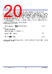
20 / 46 page  P9221-R3 Datasheet © 2017 Integrated Device Technology, Inc. 20 October 20, 2017 8.12 Received Power Packet Offset and Gain Calibration – RPPO and RPPG The received power packet offset (RPPO) and received power packet gain (RPPG) calibrations utilize dedicated pins for tuning foreign object detection (FOD). These calibrations tune the received power packet via the voltage levels on the RPPO and RPPG pins, which are determined by the external resistors in divider networks on the 1.8V bias voltage. The voltage level on the RPPO pin is used to add offset in order to shift the Received Power Packet (RPP) globally, and the voltage level on the RPPG pin adjusts the slope gain of the Received Power Packet (RPP). The received power packet offset calibration can be tuned by varying the voltage on the RPPO pin from 0.1V to 2.1V corresponding to a power offset range from -1.56W to 2.34W. The received power packet gain can be tuned by varying the voltage on the RPPG pin from 0.1V to 2.1V corresponding to a gain setting in the range from 0.111 to 2.33. To disable the FOD, the RPP0 and RPPG must be connected to GND. The RPP is adjusted according to Equation 2: RPP [mW] = Pmeasured [mW] × RPPG [%] 1755 [%] + RPPO [mW] – 1755 [mW] Equation 2 Where RPP = Reported Received Power Pmeasured = measured power from output voltage and current RPPO [mW] = VRPPO [V] 2.1 [V] × 4095 [mW] Equation 3 RPPG [%] = VRPPG [V] 2.1 [V] × 4095 [%] Equation 4 For example, if the voltage on the RPPO and RPPG pins is 0.9V then the RPP will have no offset or gain. The RPP will be exactly the same as the measured power in the receiver. |
|
链接网址 |
| ALLDATASHEET是否为您带来帮助? [ DONATE ] |
关于 Alldatasheet | 广告服务 | 联系我们 | 隐私政策 | 数据表链接 | 链接交换 | 制造商名单 All Rights Reserved©Alldatasheet.com |
| Russian : Alldatasheetru.com | Korean : Alldatasheet.co.kr | Spanish : Alldatasheet.es | French : Alldatasheet.fr | Italian : Alldatasheetit.com Portuguese : Alldatasheetpt.com | Polish : Alldatasheet.pl | Vietnamese : Alldatasheet.vn Indian : Alldatasheet.in | Mexican : Alldatasheet.com.mx | British : Alldatasheet.co.uk | New Zealand : Alldatasheet.co.nz |
|
Family Site : ic2ic.com |
icmetro.com |
 Chinese ▼
 English
 Chinese
 German
 Japanese
 Russian
 Korean
 Spanish
 French
 Italian
 Portuguese
 Polish
 Vietnamese
 Indian
 Mexican
 British
 New Zealand