|
数据搜索系统,热门电子元器件搜索 |
|
|
数据搜索系统,热门电子元器件搜索 |
|
AD8330ACP-R2 数据表(PDF) 25 Page - Analog Devices |
|
|
|||||||||||||||||||||||||||||
AD8330ACP-R2 数据表(HTML) 25 Page - Analog Devices |
|
|
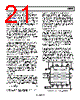
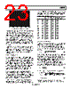
25 / 32 page  AD8330 Rev. C | Page 25 of 32 APPLICATIONS The AD8330’s versatility, very constant ac response over a wide range of gains, large signal dynamic range, output swing, single supply operation, and low power consumption commend this VGA to a diverse variety of applications. Only a few can be de- scribed here, including the most basic uses and some unusual ones. ADC DRIVING The AD8330 is well-suited to drive a high speed converter. There are many high speed converters available, but to illus- trate the general features, the example in this data sheet uses one of the least expensive, the AD9214. This is available in three grades for operation at 65 MHz, 80 MHz, and 105 MHz; the AD9214BRS-80 is a good complement to the general capabili- ties of this VGA. Figure 63 shows the connections to drive an ADC. A 3.3 V supply is used for both parts. The ADC requires that its input pins be positioned at one third of the supply, or 1.1 V. Given that the default output level of the VGA is one half the supply or 1.65 V, a small correction is introduced by the 8 kΩ resistor from CNTR to ground. The ADC specifications require that the common-mode input be within ±0.2 V of the nominal 1.1 V; variations of up to ±20% in the AD8330 on chip resistors change this voltage by only ±70 mV. With the connections shown, the AD9214 is able to receive an input of 2 V p-p; the peak output of the AD8330 can be reduced if desired by adding a resistor from VMAG to ground. An overrange condition is signaled by a high state on pin OR of the AD9214. DFS/GAIN is unconnected in this example producing an offset-binary output. To provide a twos complement output, it should be connected to the REF pin. For ADCs running at sampling rates substantially below the bandwidth of the AD8330, an intervening noise filter is recommended to limit the noise bandwidth. A one-pole filter can easily be created with a single differential capacitor between OPHI and OPLO outputs. For a corner frequency of fC, the capacitor should have a value of CFILT = 1/942 fC (26) For example, a 10 MHz corner requires about 100 pF. SIMPLE AGC AMPLIFIER Figure 64 illustrates the use of the inverted gain mode and the offset gain range (0.2 V < VDBS < 1.7 V) in supporting a low cost AGC loop. Q1 is used as a detector. When OPHI is sufficiently higher than CNTR, due to the signal swing, it conducts and charges C1. This raises VDBS and rapidly lowers the gain. Note that MODE is grounded (see Figure 48). The minimum voltage needed across R1 to set up the full gain is 0.2 V because CMGN is dc open-circuited (this does not alter VMAG) and the maximum voltage is 1.7 V. COMM OPHI INLO OPLO INHI VPSI VPSO CMOP MODE VDBS CMGN OFST CNTR ENBL VPOS BIAS AND V-REF CM MODE AND OFFSET CONTROL OUTPUT STAGES OUTPUT CONTROL VGA CORE AD9214BRS-80 D0 D1 D2 D3 D4 D5 D6 D7 D8 D9 DGND CLK AGND CLOCK REF 0.1µF REFSENSE NC ANALOG GROUND AIN AIN DFS/GAIN PWRDN DIGITAL GROUND GAIN BIAS, VDBS, 0V–1.5V NC INPUT, ±2V MAX 0.1µF 10Ω GAIN INTERFACE CHPF 8kΩ 0.1µF 0.1µF AVDD OR DrVDD 3.3Ω OVER- RANGE 3.3Ω 0.1µF VS,3.3V VMAG Figure 63. Driving an Analog-to-Digital Converter (Preliminary) |
|
链接网址 |
| ALLDATASHEET是否为您带来帮助? [ DONATE ] |
关于 Alldatasheet | 广告服务 | 联系我们 | 隐私政策 | 数据表链接 | 链接交换 | 制造商名单 All Rights Reserved©Alldatasheet.com |
| Russian : Alldatasheetru.com | Korean : Alldatasheet.co.kr | Spanish : Alldatasheet.es | French : Alldatasheet.fr | Italian : Alldatasheetit.com Portuguese : Alldatasheetpt.com | Polish : Alldatasheet.pl | Vietnamese : Alldatasheet.vn Indian : Alldatasheet.in | Mexican : Alldatasheet.com.mx | British : Alldatasheet.co.uk | New Zealand : Alldatasheet.co.nz |
|
Family Site : ic2ic.com |
icmetro.com |
 Chinese ▼
 English
 Chinese
 German
 Japanese
 Russian
 Korean
 Spanish
 French
 Italian
 Portuguese
 Polish
 Vietnamese
 Indian
 Mexican
 British
 New Zealand