|
数据搜索系统,热门电子元器件搜索 |
|
|
数据搜索系统,热门电子元器件搜索 |
|
SSM2211CP-R2 数据表(PDF) 15 Page - Analog Devices |
|
|
|||||||||||||||||||||||||||||
SSM2211CP-R2 数据表(HTML) 15 Page - Analog Devices |
|
|
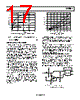
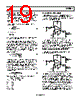
15 / 24 page  SSM2211 Rev. D | Page 15 of 24 TYPICAL APPLICATIONS SSM2211 AUDIO INPUT SPEAKER 8V RF CS 5V 2 7 1 8 5 6 4 3 – + CC RI CB – + Figure 42. Typical Configuration Figure 42 shows how the SSM2211 is connected in a typical application. The SSM2211 can be configured for gain much like a standard operational amplifier. The gain from the audio input to the speaker is I F V R R A × = 2 (1) The 2× factor comes from the fact that Pin 8 has the opposite polarity of Pin 5, providing twice the voltage swing to the speaker from the bridged-output configuration. CS is a supply bypass capacitor used to provide power supply filtering. Pin 2 is connected to Pin 3 to provide an offset voltage for single-supply use, with CB providing a low ac impedance to ground to help power supply rejection. Because Pin 4 is a virtual ac ground, the input impedance is equal to RI. CC is the input coupling capacitor, which also creates a high-pass filter with a corner frequency of C I HP C R f × π = 2 1 (2) Because the SSM2211 has an excellent phase margin, a feedback capacitor in parallel with RF to band limit the amplifier is not required, as it is in some competitor products. BRIDGED OUTPUT VS. SINGLE-ENDED OUTPUT CONFIGURATIONS The power delivered to a load with a sinusoidal signal can be expressed in terms of the peak voltage of the signal and the resistance of the load as L PK L R V P × = 2 2 (3) By driving a load from a bridged-output configuration, the voltage swing across the load doubles. Therefore, an advantage in using a bridged-output configuration becomes apparent from Equation 3, as doubling the peak voltage results in four times the power delivered to the load. In a typical application operating from a 5 V supply, the maximum power that can be delivered by the SSM2211 to an 8 Ω speaker in a single-ended configuration is 250 mW. By driving this speaker with a bridged output, 1 W of power can be delivered. This translates to a 12 dB increase in sound pressure level from the speaker. Driving a speaker differentially from a bridged output offers another advantage in that it eliminates the need for an output coupling capacitor to the load. In a single-supply application, the quiescent voltage at the output is half of the supply voltage. If a speaker is connected in a single-ended configuration, a coupling capacitor is needed to prevent dc current from flowing through the speaker. This capacitor also needs to be large enough to prevent low frequency roll-off. The corner frequency is given by C L C R f × = − π 2 1 dB 3 (4) where RL is the speaker resistance and CC is the coupling capacitance. For an 8 Ω speaker and a corner frequency of 20 Hz, a 1000 μF capacitor would be needed, which is physically large and costly. By connecting a speaker in a bridged-output configuration, the quiescent differential voltage across the speaker becomes nearly zero, eliminating the need for the coupling capacitor. SPEAKER EFFICIENCY AND LOUDNESS The effective loudness of 1 W of power delivered into an 8 Ω speaker is a function of speaker efficiency. The efficiency is typically rated as the sound pressure level (SPL) at 1 meter in front of the speaker with 1 W of power applied to the speaker. Most speakers are between 85 dB and 95 dB SPL at 1 meter at 1 W. Table 7 shows a comparison of the relative loudness of different sounds. Table 7. Typical Sound Pressure Levels Source of Sound dB SPL Threshold of Pain 120 Heavy Street Traffic 95 Cabin of Jet Aircraft 80 Average Conversation 65 Average Home at Night 50 Quiet Recording Studio 30 Threshold of Hearing 0 It can easily be seen that 1 W of power into a speaker can produce quite a bit of acoustic energy. |
|
|
链接网址 |
| ALLDATASHEET是否为您带来帮助? [ DONATE ] |
关于 Alldatasheet | 广告服务 | 联系我们 | 隐私政策 | 数据表链接 | 链接交换 | 制造商名单 All Rights Reserved©Alldatasheet.com |
| Russian : Alldatasheetru.com | Korean : Alldatasheet.co.kr | Spanish : Alldatasheet.es | French : Alldatasheet.fr | Italian : Alldatasheetit.com Portuguese : Alldatasheetpt.com | Polish : Alldatasheet.pl | Vietnamese : Alldatasheet.vn Indian : Alldatasheet.in | Mexican : Alldatasheet.com.mx | British : Alldatasheet.co.uk | New Zealand : Alldatasheet.co.nz |
|
Family Site : ic2ic.com |
icmetro.com |
 Chinese ▼
 English
 Chinese
 German
 Japanese
 Russian
 Korean
 Spanish
 French
 Italian
 Portuguese
 Polish
 Vietnamese
 Indian
 Mexican
 British
 New Zealand