|
数据搜索系统,热门电子元器件搜索 |
|
|
数据搜索系统,热门电子元器件搜索 |
|
SSM2211CP-R2 数据表(PDF) 19 Page - Analog Devices |
|
|
|||||||||||||||||||||||||||||
SSM2211CP-R2 数据表(HTML) 19 Page - Analog Devices |
|
|
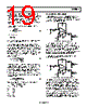
19 / 24 page  SSM2211 Rev. D | Page 19 of 24 voltage reference. The extra supply voltage also allows the SSM2211 to reproduce peaks in excess of 1 W without clipping the signal. With VDD = 5 V and RL = 8 Ω, Equation 9 shows that the maximum power dissipation for the SSM2211 is 633 mW. From the power derating curve in Figure 31, the ambient temperature must be less than 73°C for the SOIC and 118°C for the LFCSP. The required gain of the amplifier can be determined from Equation 17 as 8 . 2 = × = rms IN, L L V V R P A (17) From Equation 1 2 V I F A R R = or RF = 1.4 × RI. Because the desired input impedance is 20 kΩ, RI = 20 kΩ and R2 = 28 kΩ. The final design step is to select the input capacitor. When adding an input capacitor, CC, to create a high-pass filter, the corner frequency needs to be far enough away for the design to meet the bandwidth criteria. For a first-order filter to achieve a pass-band response within 0.25 dB, the corner frequency must be at least 4.14× away from the pass-band frequency. So, (4.14 × fHP) < 20 Hz. Using Equation 2, the minimum size of input capacitor can be found. ⎟⎟ ⎠ ⎞ ⎜⎜ ⎝ ⎛ × > 14 4 Hz 20 kΩ 20 π 2 1 . C C (18) Therefore, CC > 1.65 μF. Using a 2.2 μF is a practical choice for CC. The gain bandwidth product for each internal amplifier in the SSM2211 is 4 MHz. Because 4 MHz is much greater than 4.14 × 20 kHz, the design meets the upper frequency bandwidth criteria. The SSM2211 can also be configured for higher differential gains without running into bandwidth limitations. Equation 16 shows an appropriate value for CB to reduce start- up popping noise. ( )( ) μF 76 1 kΩ 25 kΩ 20 μF 2 2 . . C B = > (19) Selecting CB to be 2.2 μF for a practical value of capacitor minimizes start-up popping noise. To summarize the final design: VDD 5 V R1 20 kΩ RF 28 kΩ C SINGLE-ENDED APPLICATIONS There are applications in which driving a speaker differentially is not practical, for example, a pair of stereo speakers where the minus terminal of both speakers is connected to ground. Figure 48 shows how this can be accomplished. SSM2211 5V 2 7 1 8 5 6 4 3 0.47 μF 470 μF + – + – 10k Ω 10k Ω 250mW SPEAKER (8 Ω) AUDIO INPUT 0.1 μF SSM2211 5V 2 7 1 8 5 6 4 3 0.47 μF 470 μF + – + – 10k Ω 10k Ω 250mW SPEAKER (8 Ω) AUDIO INPUT 0.1 μF Figure 48. Single-Ended Output Application It is not necessary to connect a dummy load to the unused output to help stabilize the output. The 470 μF coupling capacitor creates a high-pass frequency cutoff of 42 Hz, as given in Equation 4, which is acceptable for most computer speaker applications. The overall gain for a single-ended output configuration is AV = RF/R1, which for this example is equal to 1. DRIVING TWO SPEAKERS SINGLE ENDEDLY It is possible to drive two speakers single endedly with both outputs of the SSM2211. SSM2211 5V 2 7 1 8 5 6 4 3 1 μF 470 μF + – + – 20k Ω 20k Ω RIGHT SPEAKER (8 Ω) AUDIO INPUT 0.1 μF 470 μF LEFT SPEAKER (8 Ω) Figure 49. SSM2211 Used as a Dual-Speaker Amplifier Each speaker is driven by a single-ended output. The trade-off is that only 250 mW of sustained power can be put into each speaker. Also, a coupling capacitor must be connected in series with each of the speakers to prevent large dc currents from flowing through the 8 Ω speakers. These coupling capacitors produce a high-pass filter with a corner frequency given by Equation 4. For a speaker load of 8 Ω and a coupling capacitor of 470 μF, this results in a −3 dB frequency of 42 Hz. Because the power of a single-ended output is one-quarter that of a bridged output, both speakers together are still half as loud (−6 dB SPL) as a single speaker driven with a bridged output. C 2.2 μF CB 2.2 μF TA, MAX 85°C |
|
|
链接网址 |
| ALLDATASHEET是否为您带来帮助? [ DONATE ] |
关于 Alldatasheet | 广告服务 | 联系我们 | 隐私政策 | 数据表链接 | 链接交换 | 制造商名单 All Rights Reserved©Alldatasheet.com |
| Russian : Alldatasheetru.com | Korean : Alldatasheet.co.kr | Spanish : Alldatasheet.es | French : Alldatasheet.fr | Italian : Alldatasheetit.com Portuguese : Alldatasheetpt.com | Polish : Alldatasheet.pl | Vietnamese : Alldatasheet.vn Indian : Alldatasheet.in | Mexican : Alldatasheet.com.mx | British : Alldatasheet.co.uk | New Zealand : Alldatasheet.co.nz |
|
Family Site : ic2ic.com |
icmetro.com |
 Chinese ▼
 English
 Chinese
 German
 Japanese
 Russian
 Korean
 Spanish
 French
 Italian
 Portuguese
 Polish
 Vietnamese
 Indian
 Mexican
 British
 New Zealand