|
数据搜索系统,热门电子元器件搜索 |
|
|
数据搜索系统,热门电子元器件搜索 |
|
CC1070-RTY1 数据表(PDF) 18 Page - Texas Instruments |
|
|
|||||||||||||||||||||||||||||
CC1070-RTY1 数据表(HTML) 18 Page - Texas Instruments |
|
|
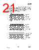
18 / 57 page  CC1070 SWRS043A Page 18 of 54 9.1 4-wire Serial Configuration Interface CC1070 is configured via a simple 4-wire SPI-compatible interface (PDI, PDO, PCLK and PSEL) where CC1070 is the slave. There are 22 8-bit configuration registers and 6 8-bit test-only registers, each addressed by a 7-bit address. A Read/Write bit initiates a read or write operation. A full configuration of CC1070 requires sending 22 data frames of 16 bits each (7 address bits, R/W bit and 8 data bits). The time needed for a full configuration depends on the PCLK frequency. With a PCLK frequency of 10 MHz the full configuration is done in less than 36 µs. Setting the device in power down mode requires sending one frame only and will in this case take less than 2 µs. All registers are also readable. In each write-cycle, 16 bits are sent on the PDI-line. The seven most significant bits of each data frame (A6:0) are the address- bits. A6 is the MSB (Most Significant Bit) of the address and is sent as the first bit. The next bit is the R/W bit (high for write, low for read). The 8 data-bits are then transferred (D7:0). During address and data transfer the PSEL (Program SELect) must be kept low. See Figure 6. The timing for the programming is also shown in Figure 6 with reference to Table 11. The clocking of the data on PDI is done on the positive edge of PCLK. Data should be set up on the negative edge of PCLK by the microcontroller. When the last bit, D0, of the 8 data-bits has been loaded, the data word is loaded in the internal configuration register. The configuration data will be retained during a programmed power-down mode, but not when the power-supply is turned off. The registers can be programmed in any order. The configuration registers can also be read by the microcontroller via the same configuration interface. The seven address bits are sent first, then the R/W bit set low to initiate the data read-back. CC1070 then returns the data from the addressed register. PDO is used as the data output and must be configured as an input by the microcontroller. The PDO is set at the negative edge of PCLK and should be sampled at the positive edge. The read operation is illustrated in Figure 7. PSEL must be set high between each read/write operation. There are also 5 read-only status registers. |
|
链接网址 |
| ALLDATASHEET是否为您带来帮助? [ DONATE ] |
关于 Alldatasheet | 广告服务 | 联系我们 | 隐私政策 | 数据表链接 | 链接交换 | 制造商名单 All Rights Reserved©Alldatasheet.com |
| Russian : Alldatasheetru.com | Korean : Alldatasheet.co.kr | Spanish : Alldatasheet.es | French : Alldatasheet.fr | Italian : Alldatasheetit.com Portuguese : Alldatasheetpt.com | Polish : Alldatasheet.pl | Vietnamese : Alldatasheet.vn Indian : Alldatasheet.in | Mexican : Alldatasheet.com.mx | British : Alldatasheet.co.uk | New Zealand : Alldatasheet.co.nz |
|
Family Site : ic2ic.com |
icmetro.com |
 Chinese ▼
 English
 Chinese
 German
 Japanese
 Russian
 Korean
 Spanish
 French
 Italian
 Portuguese
 Polish
 Vietnamese
 Indian
 Mexican
 British
 New Zealand