|
数据搜索系统,热门电子元器件搜索 |
|
|
数据搜索系统,热门电子元器件搜索 |
|
CS2000-CP 数据表(PDF) 14 Page - Cirrus Logic |
|
|
|||||||||||||||||||||||||||||
CS2000-CP 数据表(HTML) 14 Page - Cirrus Logic |
|
|
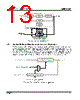
14 / 36 page  CS2000-CP 14 DS761F1 5. APPLICATIONS 5.1 Timing Reference Clock Input The low jitter timing reference clock (RefClk) can be provided by either an external reference clock or an external crystal in conjunction with the internal oscillator. In order to maintain a stable and low-jitter PLL out- put the timing reference clock must also be stable and low-jitter; the quality of the timing reference clock directly affects the performance of the PLL and hence the quality of the PLL output. 5.1.1 Internal Timing Reference Clock Divider The Internal Timing Reference Clock (SysClk) has a smaller maximum frequency than what is allowed on the XTI/REF_CLK pin. The CS2000 supports the wider external frequency range by offering an internal divider for RefClk. The RefClkDiv[1:0] bits should be set such that SysClk, the divided RefClk, then falls within the valid range as indicated in “AC Electrical Characteristics” on page 8. It should be noted that the maximum allowable input frequency of the XTI/REF_CLK pin is dependent upon its configuration as either a crystal connection or external clock input. See the “AC Electrical Char- acteristics” on page 8 for more details. For the lowest possible output jitter, attention should be paid to the absolute frequency of the Timing Ref- erence Clock relative to the PLL Output frequency (CLK_OUT). To minimize output jitter, the Timing Ref- erence Clock frequency should be chosen such that fRefClk is at least +/-15 kHz from fCLK_OUT*N/32 where N is an integer. Figure 11 shows the effect of varying the RefClk frequency around fCLK_OUT*N/32. It should be noted that there will be a jitter null at the zero point when N = 32 (not shown in Figure 11). An example of how to determine the range of RefClk frequencies around 12 MHz to be used in order to achieve the lowest jitter PLL output at a frequency of 12.288 MHz is as follows: where: and Referenced Control Register Location RefClkDiv[1:0] ....................... “Reference Clock Input Divider (RefClkDiv[1:0])” on page 32 Figure 10. Internal Timing Reference Clock Divider N Internal Timing Reference Clock PLL Output Fractional-N Frequency Synthesizer Timing Reference Clock Divider ÷1 ÷2 ÷4 XTI/REF_CLK RefClkDiv[1:0] 8 MHz < SysClk < 14 MHz 8 MHz < RefClk < Timing Reference Clock 50 MHz (XTI) 58 MHz (REF_CLK) -80 -60 -40 -20 0 20 40 60 80 20 40 60 80 100 120 140 160 180 Normalized REF__CLK Frequency (kHz) CLK__OUT Jitter -15 kHz +15 kHz CLK__OUT f *32/N Figure 11. REF_CLK Frequency vs a Fixed CLK_OUT f L f RefClk f H ≤≤ f L f CLK_OUT 31 32 ------15kHz + × = 12.288MHz 0.96875 15kHz + × = 11.919MHz = f H f CLK_OUT 32 32 ------15kHz – × = 12.288MHz 115kHz + × = 12.273MHz = |
|
链接网址 |
| ALLDATASHEET是否为您带来帮助? [ DONATE ] |
关于 Alldatasheet | 广告服务 | 联系我们 | 隐私政策 | 数据表链接 | 链接交换 | 制造商名单 All Rights Reserved©Alldatasheet.com |
| Russian : Alldatasheetru.com | Korean : Alldatasheet.co.kr | Spanish : Alldatasheet.es | French : Alldatasheet.fr | Italian : Alldatasheetit.com Portuguese : Alldatasheetpt.com | Polish : Alldatasheet.pl | Vietnamese : Alldatasheet.vn Indian : Alldatasheet.in | Mexican : Alldatasheet.com.mx | British : Alldatasheet.co.uk | New Zealand : Alldatasheet.co.nz |
|
Family Site : ic2ic.com |
icmetro.com |
 Chinese ▼
 English
 Chinese
 German
 Japanese
 Russian
 Korean
 Spanish
 French
 Italian
 Portuguese
 Polish
 Vietnamese
 Indian
 Mexican
 British
 New Zealand