|
数据搜索系统,热门电子元器件搜索 |
|
|
数据搜索系统,热门电子元器件搜索 |
|
AD7450ARM 数据表(PDF) 14 Page - Analog Devices |
|
|
|||||||||||||||||||||||||||||
AD7450ARM 数据表(HTML) 14 Page - Analog Devices |
|
|
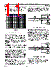
14 / 24 page  REV. PrJ PRELIMINARY TECHNICAL DATA –14– AD7450 VDD C1 D D VIN+ R1 C2 VIN- R1 C2 VDD D D C1 Figure 11. Equivalent Analog Input Circuit. Conversion Phase - Switches Open Track Phase - Switches Closed When no amplifier is used to drive the analog input, the source impedance should be limited to low values. The maximum source impedance will depend on the amount of Total Harmonic Distortion (THD) that can be tolerated. The THD will increase as the source impedance increases and performance will degrade. Figure 12 shows a graph of the THD versus analog input signal frequency for dif- ferent source impedances. TITLE 0 0 0 00 0 00 0 0 Figure 12.THD vs Analog Input Frequency for Various Source Impedances TBD Figure 13 shows a graph of THD versus analog input frequency for VDD of 5V and 3V, while sampling at 1MHz and 833kHz with a SCLK of 18 MHz and 15MHz respectively. TIT LE 0 0 0 0 0 0 00 0 0 Figure 13.THD vs Analog Input Frequency for 3V and 5V Supply Voltages TBD DRIVING DIFFERENTIAL INPUTS Differential operation requires that VIN+ and VIN- be si- multaneously driven with two equal signals that are 180 o out of phase. The common mode must be set up exter- nally and has a range which is determined by VREF, the power supply and the particular amplifier used to drive the analog inputs (see figure 8). Differential modes of opera- tion with either an ac or dc input, provide the best THD performance over a wide frequency range. Since not all applications have a signal preconditioned for differential operation, there is often a need to perform single ended to differential conversion. Differential Amplifier An ideal method of applying dc differential drive to the AD7450 is to use a differential amplifier such as the AD8138. This part can be used as a single ended to differential amplifier or as a differential to differential amplifier. In both cases the analog input needs to be bipolar. It also provides common mode level shifting and buffering of the bipolar input signal. Figure 14 shows how the AD8138 can be used as a single ended to differential amplifier. The positive and negative outputs of the AD8138 are connected to the respec- tive inputs on the ADC via a pair of series resistors to minimize the effects of switched capacitance on the front end of the ADC. The RC low pass filter on each analog input is recommended in ac applications to remove high frequency components of the analog input. The architecture of the AD8138 results in outputs that are very highly balanced over a wide frequency range without requiring tightly matched external components. If the analog input source being used has no impedance then all four resistors (Rg1, Rg2, Rf1, Rf2) should be the same. If the source has a 50 impedance and a 50 termination for example, the value of Rg2 should be increased by 25 to balance this parallel impedance on the input and thus ensure that both the positive and negative analog inputs have the same gain (see figure 14). The outputs of the amplifier are perfectly matched, balanced differential outputs of identical amplitude and are exactly 180 o out of phase. |
|
|
链接网址 |
| ALLDATASHEET是否为您带来帮助? [ DONATE ] |
关于 Alldatasheet | 广告服务 | 联系我们 | 隐私政策 | 数据表链接 | 链接交换 | 制造商名单 All Rights Reserved©Alldatasheet.com |
| Russian : Alldatasheetru.com | Korean : Alldatasheet.co.kr | Spanish : Alldatasheet.es | French : Alldatasheet.fr | Italian : Alldatasheetit.com Portuguese : Alldatasheetpt.com | Polish : Alldatasheet.pl | Vietnamese : Alldatasheet.vn Indian : Alldatasheet.in | Mexican : Alldatasheet.com.mx | British : Alldatasheet.co.uk | New Zealand : Alldatasheet.co.nz |
|
Family Site : ic2ic.com |
icmetro.com |
 Chinese ▼
 English
 Chinese
 German
 Japanese
 Russian
 Korean
 Spanish
 French
 Italian
 Portuguese
 Polish
 Vietnamese
 Indian
 Mexican
 British
 New Zealand