|
数据搜索系统,热门电子元器件搜索 |
|
|
数据搜索系统,热门电子元器件搜索 |
|
ST1S31D-R 数据表(PDF) 18 Page - STMicroelectronics |
|
|
|||||||||||||||||||||||||||||
ST1S31D-R 数据表(HTML) 18 Page - STMicroelectronics |
|
|
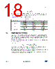
18 / 35 page  Application information ST1S31 18/35 DocID022998 Rev 4 Equation 22 So if the inductor value decreases, the peak current (which must be lower than the current limit of the device) increases. The higher the inductor value, the higher the average output current that can be delivered, without reaching the current limit. In Table 7 some inductor part numbers are listed. 5.3 Output capacitor selection The current in the output capacitor has a triangular waveform which generates a voltage ripple across it. This ripple is due to the capacitive component (charge or discharge of the output capacitor) and the resistive component (due to the voltage drop across its ESR). So the output capacitor must be selected in order to have a voltage ripple compliant with the application requirements. The amount of the voltage ripple can be calculated starting from the current ripple obtained by the inductor selection. Equation 23 For a ceramic (MLCC) capacitor, the capacitive component of the ripple dominates the resistive one. While for an electrolytic capacitor the opposite is true. As the compensation network is internal, the output capacitor should be selected in order to have a proper phase margin and then a stable control loop. The equations of Section 5.2 help to check loop stability given the application conditions, the value of the inductor and of the output capacitor. Table 7. Inductors Manufacturer Series Inductor value ( µH) Saturation current (A) Coilcraft XAL50xx 1.2 to 3.3 6.3 to 9 XAL60xx 2.2 to 5.6 7.4 to 11 MSS1048 1.0 to 3.8 6.5 to 11 Würth WE-HCI 7030 1.5 to 4.7 7 to 14 WE-PD type L 1.5 to 3.5 6.4 to 10 Coiltronics DR73 1.0 to 2.2 5.5 to7.9 DR74 1.5 to 3.3 5.4 to 8.35 ILPK IO I L 2 -------- + = V OUT ESR I MAX I MAX 8COUT fSW ------------------------------------- + = |
|
链接网址 |
| ALLDATASHEET是否为您带来帮助? [ DONATE ] |
关于 Alldatasheet | 广告服务 | 联系我们 | 隐私政策 | 数据表链接 | 链接交换 | 制造商名单 All Rights Reserved©Alldatasheet.com |
| Russian : Alldatasheetru.com | Korean : Alldatasheet.co.kr | Spanish : Alldatasheet.es | French : Alldatasheet.fr | Italian : Alldatasheetit.com Portuguese : Alldatasheetpt.com | Polish : Alldatasheet.pl | Vietnamese : Alldatasheet.vn Indian : Alldatasheet.in | Mexican : Alldatasheet.com.mx | British : Alldatasheet.co.uk | New Zealand : Alldatasheet.co.nz |
|
Family Site : ic2ic.com |
icmetro.com |
 Chinese ▼
 English
 Chinese
 German
 Japanese
 Russian
 Korean
 Spanish
 French
 Italian
 Portuguese
 Polish
 Vietnamese
 Indian
 Mexican
 British
 New Zealand