|
数据搜索系统,热门电子元器件搜索 |
|
|
数据搜索系统,热门电子元器件搜索 |
|
KSZ9563R 数据表(PDF) 209 Page - Microchip Technology |
|
|
|||||||||||||||||||||||||||||
KSZ9563R 数据表(HTML) 209 Page - Microchip Technology |
|
|
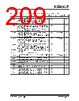
209 / 226 page  2017-2018 Microchip Technology Inc. DS00002419D-page 209 KSZ9563R TABLE 6-11: TRIGGER OUTPUT UNIT AND TIMESTAMP INPUT UNIT TIMING VALUES Symbol Description Min Typ Max Units Trigger Output Unit Timing (Cascade Mode) tCASP1 In cascade mode for TRIGX_CFG_1[6:4] = 100, or 101, or 110 (Neg. Edge, Pos. Edge, and Shift Reg. Output signals). Minimum time between start of one TOU and the start of another TOU cascaded on the same GPIO pin. 80 ns tCASP2 In cascade mode for TRIGX_CFG_1[6:4] = 010, 011, 100, or 101 (Neg. Pulse, Pos. Pulse, Neg. Periodic, and Pos. Periodic Output signals). Minimum time between start of one TOU and the start of another TOU cascaded on the same GPIO pin. 120 ns tCYCCASP In cascade mode for TRIGX_CFG_1[6:4] = 010, and 011 (Neg. Pulse, Pos. Pulse Output signals). In cascade mode, the cycle time of the trigger output unit oper- ating in the indicated modes. 80 32 + PWIDTH2 ns tCYCNC1 In cascade mode for TRIGX_CFG_1[6:4] = 100 or 101 (Neg. Periodic, Pos. periodic Output signals). Minimum cycle time for any trigger output unit operating in the indicated modes. 80 32 + PWIDTH2 ns tGAP23 In cascade mode for TRIGX_CFG_1[6:4] = 010, and 011 (Neg. Pulse, Pos. Pulse Output signals): Minimum gap time required between end of period of first trig- ger output unit to beginning of output of 2nd trigger output unit. 80 ns PWIDTH2 In cascade mode, the minimum low or high pulse width of the trigger output unit. 8ns Trigger Output Unit Timing (Non-Cascade Mode) tCYCNC2 In non-cascade mode, the minimum cycle time for any trigger output unit. 80 32 + PWIDTH2 ns tPOGAP In non-cascade mode, the minimum time between the end of the generated pulse to the start of the next pulse. 32 ns PWIDTH1 In non-cascade mode, the minimum low or high pulse width of the trigger output unit. 8ns Timestamp Input Unit Timing IPHIGH Allowable high time of an incoming digital waveform on any GPIO pin. 24 ns IPLOW In non-cascade mode, the minimum time between the end of the generated pulse to the start of the next pulse. 24 ns IPCYC In non-cascade mode, the minimum time between the end of the generated pulse to the start of the next pulse. 48 ns |
|
链接网址 |
| ALLDATASHEET是否为您带来帮助? [ DONATE ] |
关于 Alldatasheet | 广告服务 | 联系我们 | 隐私政策 | 数据表链接 | 链接交换 | 制造商名单 All Rights Reserved©Alldatasheet.com |
| Russian : Alldatasheetru.com | Korean : Alldatasheet.co.kr | Spanish : Alldatasheet.es | French : Alldatasheet.fr | Italian : Alldatasheetit.com Portuguese : Alldatasheetpt.com | Polish : Alldatasheet.pl | Vietnamese : Alldatasheet.vn Indian : Alldatasheet.in | Mexican : Alldatasheet.com.mx | British : Alldatasheet.co.uk | New Zealand : Alldatasheet.co.nz |
|
Family Site : ic2ic.com |
icmetro.com |
 Chinese ▼
 English
 Chinese
 German
 Japanese
 Russian
 Korean
 Spanish
 French
 Italian
 Portuguese
 Polish
 Vietnamese
 Indian
 Mexican
 British
 New Zealand