|
数据搜索系统,热门电子元器件搜索 |
|
|
数据搜索系统,热门电子元器件搜索 |
|
ADL5960ACCZ-R2 数据表(PDF) 20 Page - Analog Devices |
|
|
|||||||||||||||||||||||||||||
ADL5960ACCZ-R2 数据表(HTML) 20 Page - Analog Devices |
|
|
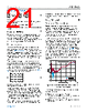
20 / 32 page  Data Sheet ADL5960 THEORY OF OPERATION analog.com Rev. A | 20 of 32 Figure 56. Error Model for One-Port S-Parameter Measurements The flow diagram provides a more detailed description of the various error contributions that cause the measured reflection coef- ficient, ΓM=b0/a0,todifferfromtheactualreflectioncoefficient, Γ=b1/a1.Thefactor,e11,representsimpedancemismatchof the VNA port (from 50 Ω). A fraction of b1 is reflected back to the load. The e01 and e10 factors represent the tracking error. In relation to the ADL5960, the tracking error comprises insertion loss of the bridge, the conversion gain from RFIN to IFFx and RFOUT to IFRx, as well as the mismatch in conversion gain between the channels. Finally, e00 represents the finite directivity of a practical VNA, a measure for the ability to separate the forward and reverse traveling power waves. If the load is a perfect 50 Ω, then b1 = 0 and an ideal VNA measures b0 = 0. However, in a practical VNA, the directivity is finite and some signal leaks from the forward path to the reverse path. Using Figure 56, the measured reflection coefficient can be ex- pressed in terms of the error coefficients and the reflection coeffi- cient of the load as follows: ΓM=e00+ e01e101−Γe11Γ (7) Equation 7 can be rearranged into a linear expression for the error coefficients as follows: e00−ΔeΓ+e11ΓM=ΓM Δe=e00e11−e01e10 (8) A calibration procedure that measures three different known loads, that is, collects three combinations of measured and actual reflec- tion coefficients, can then be used to calculate the error coefficients as follows: 1−Γ1ΓM1 1−Γ2ΓM2 1−Γ3ΓM3T e00Δee11 e = ΓM1ΓM2ΓM3 ΓM e=T−1ΓM (9) After the system is calibrated, the corrected reflection coefficient can be calculated from the measured coefficient by rearranging Equation 7: Γ= ΓM−e00 e11ΓM−Δe (10) Although in principle any combination of sufficiently different stand- ards can be used to calibrate the system, a combination of a short, an open, and a 50 Ω load are by far the most common choice. Note that the procedure outlined in Equation 9 needs to be repeated at every frequency point of interest. Two-Port Calibration The calibration procedure for a two-port S-parameter measurement can be explained using Figure 57. The VNA is modeled by Port 0, Port 2, and the error model. As a result of the hardware errors in the system, the measured S-parameters at Port 0 differ from the actual DUT S-parameters observed at Port 1, and the S-parameters measured at Port 2 differ from the DUT S-parameters at Port 3. As long as the error contributions scale linearly with power, the incident and reflected waves at Port 0 and Port 2 can be related to those at Port 1 and Port 3 using a block matrix, as follows: b0a0b2 a2 = T01T03 T21T23 b1a1b3 a3 (11) Figure 57. Error Model for Two-Port S-Parameter Measurements Each of the matrix elements, T in Equation 11, is a 2×2 matrix that describes the interaction between one VNA port and one DUT port, resulting in a total of 16 unknown error coefficients. A wide range of different calibration strategies are reported in literature to determine either a subset of or all of the error coefficients (matrix elements). One strategy to simplify the error model assumes that the crosstalk between the VNA channels is negligible, that is, that contributions of Port 1 to measurement errors in Port 2, and contributions of Port 3 to measurement errors in Port 0 are very small. This assumption is plausible in a VNA based on the ADL5960, because each VNA port is realized by a separate device. Interaction between the VNA channels can be minimized through careful PCB layout. For this situation, only the block matrices on the diagonal in Equation 11 have nonzero elements, resulting in the following: |
|
链接网址 |
| ALLDATASHEET是否为您带来帮助? [ DONATE ] |
关于 Alldatasheet | 广告服务 | 联系我们 | 隐私政策 | 数据表链接 | 链接交换 | 制造商名单 All Rights Reserved©Alldatasheet.com |
| Russian : Alldatasheetru.com | Korean : Alldatasheet.co.kr | Spanish : Alldatasheet.es | French : Alldatasheet.fr | Italian : Alldatasheetit.com Portuguese : Alldatasheetpt.com | Polish : Alldatasheet.pl | Vietnamese : Alldatasheet.vn Indian : Alldatasheet.in | Mexican : Alldatasheet.com.mx | British : Alldatasheet.co.uk | New Zealand : Alldatasheet.co.nz |
|
Family Site : ic2ic.com |
icmetro.com |
 Chinese ▼
 English
 Chinese
 German
 Japanese
 Russian
 Korean
 Spanish
 French
 Italian
 Portuguese
 Polish
 Vietnamese
 Indian
 Mexican
 British
 New Zealand