|
数据搜索系统,热门电子元器件搜索 |
|
|
数据搜索系统,热门电子元器件搜索 |
|
AT80C51RA2-RLSIV 数据表(PDF) 15 Page - International Rectifier |
|
|
|||||||||||||||||||||||||||||
AT80C51RA2-RLSIV 数据表(HTML) 15 Page - International Rectifier |
|
|
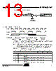
15 / 85 page  15 4188E–8051–08/06 AT/TS8xC51Rx2 5.4 Dual Data Pointer Register The additional data pointer can be used to speed up code execution and reduce code size in a number of ways. The dual DPTR structure is a way by which the chip will specify the address of an external data memory location. There are two 16-bit DPTR registers that address the external memory, and a single bit called DPS = AUXR1/bit0 (Table 5-3) that allows the program code to switch between them (Refer to Figure 5-3). Figure 5-3. Use of Dual Pointer Table 5-3. AUXR1: Auxiliary Register 1 External Data Memory AUXR1(A2H) DPS DPH(83H) DPL(82H) 0 7 DPTR0 DPTR1 AUXR1 Address 0A2H - - - - GF3 - - DPS Reset value XXXX 0 X X 0 Symbol Function - Not implemented, reserved for future use (1) 1. User software should not write 1s to reserved bits. These bits may be used in future 8051 family products to invoke new feature. In that case, the reset value of the new bit will be 0, and its active value will be 1. The value read from a reserved bit is indeterminate. GF3 will not be available on first version of the RC devices. DPS Data Pointer Selection. DPS Operating Mode 0 DPTR0 Selected 1 DPTR1 Selected GF3 This bit is a general purpose user flag(2). |
|
链接网址 |
| ALLDATASHEET是否为您带来帮助? [ DONATE ] |
关于 Alldatasheet | 广告服务 | 联系我们 | 隐私政策 | 数据表链接 | 链接交换 | 制造商名单 All Rights Reserved©Alldatasheet.com |
| Russian : Alldatasheetru.com | Korean : Alldatasheet.co.kr | Spanish : Alldatasheet.es | French : Alldatasheet.fr | Italian : Alldatasheetit.com Portuguese : Alldatasheetpt.com | Polish : Alldatasheet.pl | Vietnamese : Alldatasheet.vn Indian : Alldatasheet.in | Mexican : Alldatasheet.com.mx | British : Alldatasheet.co.uk | New Zealand : Alldatasheet.co.nz |
|
Family Site : ic2ic.com |
icmetro.com |
 Chinese ▼
 English
 Chinese
 German
 Japanese
 Russian
 Korean
 Spanish
 French
 Italian
 Portuguese
 Polish
 Vietnamese
 Indian
 Mexican
 British
 New Zealand