|
数据搜索系统,热门电子元器件搜索 |
|
|
数据搜索系统,热门电子元器件搜索 |
|
AS7331 数据表(PDF) 46 Page - OSRAM GmbH |
|
|
|||||||||||||||||||||||||||||
AS7331 数据表(HTML) 46 Page - OSRAM GmbH |
|
|
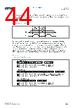
46 / 72 page  Document Feedback AS7331 Functional Description Datasheet • PUBLIC DS001047 • v4-00 • 2023-Mar-24 71 │ 45 addressed by the address pointer (REG ADDR.) before. Then acknowledge is sent by the device, and it internally increments the address pointer to the next internal register address. Each next data byte, which is transferred by the master, is sequentially stored in the internal register. If the master generates a stop condition, the transfer is aborted, and a new write sequence must be started from the beginning. 7.8.4 I²C Read Protocol The start byte consists of the slave address followed by the bit R/W set to “0” for the write direction. The first byte after the start byte is always the address pointer to the internal register, which the master wants to read and acknowledge. After that, the master sends a repeated start condition and repeats the slave address but with the bit R/W reversed. An acknowledge is then sent by the slave, which starts the data transfer to the master. The first transferred byte is the content of the internal register, which was pointed by the address pointer. Then the master acknowledges each transferred byte. The internal address pointer of the AS7331 automatically increments after each transferred register, which allows a sequential read-out of the internal registers. If a not acknowledge occurs from the master, it sends the stop condition next and the transfer is finished. A shortened read sequence is also possible, as shown in Figure 53. With the default of the bit OPTREG:INIT_IDX = “1” (see Figure 53) the internal address pointer starts at register address 2h, if the Measurement state is activated (OSR:DOS = 011b). In the case the Configuration state is activated (OSR:DOS = 010b), the internal address pointer starts at register address 0h. 7.8.5 I²C Addressable Register Space Figure 41 shows the overview of the internal registers of the AS7331, which can be accessed via the I²C interface. The control register bank can only be accessed in the configuration state, and the registers are all 8 bits long. The output registers can only be accessed in the measurement state. They are read-only registers and 16 bits long, except OUTCONV, which is 24 bits long. OUTCONV is separated into two parts to fit into the output register’s structure. OUTCONV_L contains the first lower bytes, and OUTCONV_H contains the most significant byte of OUTCONV in the first byte. The second byte is 00h. The AS7331 transfers the output data registers with the least significant byte first. The output register data transfer can start at any address. If during the sequential data read the highest possible address is achieved (CREG2:EN_TM = “0”: address 4h; CREG2:EN_TM = “1”: address 6h), the internal pointer is reset to the address 2h, so that the next transferred data byte corresponds to the low byte of MRES1. However, the maximum number of output data transferred must not exceed a total number of bytes accessible if all (6 bytes if conversion time measurement (CREG2:EN_TM) is not activated, otherwise 10 bytes). The register OUTCONV is only available in case bit CREG2:EN_TM is set to “1”. |
|
链接网址 |
| ALLDATASHEET是否为您带来帮助? [ DONATE ] |
关于 Alldatasheet | 广告服务 | 联系我们 | 隐私政策 | 数据表链接 | 链接交换 | 制造商名单 All Rights Reserved©Alldatasheet.com |
| Russian : Alldatasheetru.com | Korean : Alldatasheet.co.kr | Spanish : Alldatasheet.es | French : Alldatasheet.fr | Italian : Alldatasheetit.com Portuguese : Alldatasheetpt.com | Polish : Alldatasheet.pl | Vietnamese : Alldatasheet.vn Indian : Alldatasheet.in | Mexican : Alldatasheet.com.mx | British : Alldatasheet.co.uk | New Zealand : Alldatasheet.co.nz |
|
Family Site : ic2ic.com |
icmetro.com |
 Chinese ▼
 English
 Chinese
 German
 Japanese
 Russian
 Korean
 Spanish
 French
 Italian
 Portuguese
 Polish
 Vietnamese
 Indian
 Mexican
 British
 New Zealand