|
数据搜索系统,热门电子元器件搜索 |
|
|
数据搜索系统,热门电子元器件搜索 |
|
STDRIVE102BH 数据表(PDF) 26 Page - STMicroelectronics |
|
|
|||||||||||||||||||||||||||||
STDRIVE102BH 数据表(HTML) 26 Page - STMicroelectronics |
|
|
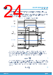
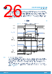
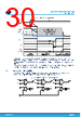
26 / 56 page  The direct mode implies that the turn-on of one driver occurs always before that the tcc,off of the complementary one is completed: the deadtime tDT on the control signals must be chosen to be smaller than the tcc,off hence tDT < 1120 ns. On the other hand, the user must select a proper deadtime, according to the total gate charge and the driving current configured in the driver. The deadtime tDT must be chosen ensuring that the VGS of the MOSFET that is turning off is equal to 0 V, before turning on the complementary MOSFET in the half-bridge. The criteria used should follow what has already been explained in Section 5.2.1.1, thus considering the total gate charge QG,tot and the IGATE,off selected. Equation 4 tDT> QG,tot IGATE,off (4) Figure 15. Current management using direct mode INH/INL -Ihold,off -Iclamp tcc,off tcc,on INHx INLx VGS,LSx VGS,HSx +Ihold,on +IGATE,on -IGATE,off hold off gate on hold on gate off clamp hold off -Ihold,off -Iclamp +Ihold,on +IGATE,on -IGATE,off tcc,off tcc,on gate on hold on hold off clamp gate off HS Current capability LS Current capability hold on tdt tdt 5.2.1.3 TCC and IGATE configuration example Figure 16 shows an example of how to configure TCC and IGATE considering that each driver drives a target MOSFET with a total gate charge QG,tot = 120 nC at 12 V of VGS. Using Igate,on = 350 mA and Igate,off = 700 mA allows to complete the charge of the gate in less than 350 ns and a discharge in less than half of the time. Therefore, selecting a tcc,off = 420 ns and tcc,on = 840 ns provides enough margin for a safe operation of the power stage. Using EN/IN mode allows the device to manage the deadtime that is 420 ns, equal to the tcc,off. According to Table 9, Table 10, and Table 11 it is possible to select the resistors to be connected to the TCC and IGATE pins, as shown in Figure 16. STDRIVE102BH, STDRIVE102H Device description DS14545 - Rev 1 page 26/56 |
|
链接网址 |
| ALLDATASHEET是否为您带来帮助? [ DONATE ] |
关于 Alldatasheet | 广告服务 | 联系我们 | 隐私政策 | 数据表链接 | 链接交换 | 制造商名单 All Rights Reserved©Alldatasheet.com |
| Russian : Alldatasheetru.com | Korean : Alldatasheet.co.kr | Spanish : Alldatasheet.es | French : Alldatasheet.fr | Italian : Alldatasheetit.com Portuguese : Alldatasheetpt.com | Polish : Alldatasheet.pl | Vietnamese : Alldatasheet.vn Indian : Alldatasheet.in | Mexican : Alldatasheet.com.mx | British : Alldatasheet.co.uk | New Zealand : Alldatasheet.co.nz |
|
Family Site : ic2ic.com |
icmetro.com |
 Chinese ▼
 English
 Chinese
 German
 Japanese
 Russian
 Korean
 Spanish
 French
 Italian
 Portuguese
 Polish
 Vietnamese
 Indian
 Mexican
 British
 New Zealand