|
数据搜索系统,热门电子元器件搜索 |
|
|
数据搜索系统,热门电子元器件搜索 |
|
STDRIVE102BH 数据表(PDF) 31 Page - STMicroelectronics |
|
|
|||||||||||||||||||||||||||||
STDRIVE102BH 数据表(HTML) 31 Page - STMicroelectronics |
|
|
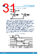
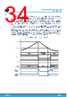
31 / 56 page  Figure 23. STDRIVE102H AFE block diagram + OA_INP CREF Op-amp Comp to Control Logic OA_INN OA_O C_IN1 + - VDD VDD AGND AGND Comp C_IN2 + - VDD AGND Deglitch filter tdg(COMP) to Control Logic Deglitch filter tdg(COMP) The operational amplifiers are unity-gain stable for load capacitors up to 100 pF and have a low input bias current. They provide a rail-to-rail input and output operation, a wide bandwidth, and a fast recovery of the output after saturation. The operational amplifiers are totally uncommitted, so they can be used as general-purpose components within their operative range (between 0 V and VDD). As an example of typical configuration, the operational amplifiers can be used to amplify the voltage drop across the shunt resistors placed on the low-side half-bridge, in order to implement a current sense on each phase. Therefore, the STDRIVE102BH is suitable for triple shunt applications, while the STDRIVE102H is suitable for single shunt applications. The comparators in the AFE, three in the STDRIVE102BH and two in the STDRIVE102H, have a single CREF pin, in common to all the negative inputs as shown in Figure 22 and Figure 23. The positive input of each comparator has a dedicated pin (C_INx). As an example of typical configuration, the comparators can be used to implement an overcurrent protection, an overvoltage protection or an overtemperature protection for the application, in case an external temperature sensor is present in the application. When the voltage on the positive input of one comparator (C_INx) exceeds the voltage on CREF for a time longer than the deglitch time (tdg(COMP)), the comparator’s output triggers the protection circuitry and raises a FAULT event, which forces the nFAULT pin low. At the same time, the power stage is disabled turning off all the external MOSFETs with the soft-off feature (see Section 5.4). The FAULT condition triggered by the comparators is latched: the normal operation is restored bringing the EN pin below the Vrelease threshold for a time longer than tEN,pulse_rel (refer to Figure 24). Figure 24. AFE comparator example tdg(COMP) < tdg(COMP) nFAULT EN Gate Drivers deglitch time CINx VCREF comparator protection FAULT latched Gate driver LOW Gate driver LOW FAULT released EN = 0 operative Gate driver active operative Gate driver active Vrelease tEN,pulse_rel STDRIVE102BH, STDRIVE102H Device description DS14545 - Rev 1 page 31/56 |
|
链接网址 |
| ALLDATASHEET是否为您带来帮助? [ DONATE ] |
关于 Alldatasheet | 广告服务 | 联系我们 | 隐私政策 | 数据表链接 | 链接交换 | 制造商名单 All Rights Reserved©Alldatasheet.com |
| Russian : Alldatasheetru.com | Korean : Alldatasheet.co.kr | Spanish : Alldatasheet.es | French : Alldatasheet.fr | Italian : Alldatasheetit.com Portuguese : Alldatasheetpt.com | Polish : Alldatasheet.pl | Vietnamese : Alldatasheet.vn Indian : Alldatasheet.in | Mexican : Alldatasheet.com.mx | British : Alldatasheet.co.uk | New Zealand : Alldatasheet.co.nz |
|
Family Site : ic2ic.com |
icmetro.com |
 Chinese ▼
 English
 Chinese
 German
 Japanese
 Russian
 Korean
 Spanish
 French
 Italian
 Portuguese
 Polish
 Vietnamese
 Indian
 Mexican
 British
 New Zealand