|
数据搜索系统,热门电子元器件搜索 |
|
|
数据搜索系统,热门电子元器件搜索 |
|
RFEVAL3-R1 数据表(PDF) 18 Page - rfsolutions.ltd |
|
|
|||||||||||||||||||||||||||||
RFEVAL3-R1 数据表(HTML) 18 Page - rfsolutions.ltd |
|
|
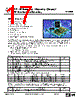
18 / 24 page  RF / IR Encoder / Decoder Chipset RF600E RF Evaluation Boards, RF600D Description The RFEVAL2 kit uses the RF600 chip set to implement the highly secure KeeLoq protocol and allows the user to experiment with this code hopping system. The kit is supplied primarily as a hardware development platform which obviates the need to construct hand-wired prototype boards which are rarely successful in creating a valid environment for the development of radio systems. The following projects can be undertaken with the kit and will allow the user to compare the performance of various transmitter/receiver combinations. 1. Three button AM fob / HiRK-433 receiver decoder module. 2. Three button AM fob / AM-RRS3-433 receiver, RF600D decoder. Serial and parallel outputs. 3. Four button FM encoder with / FM-RTFQ1-433 / RF600D decoder. Serial and parallel outputs. The RFEVAL2 evaluation board contains seven main areas of circuitry. The board allows the user to connect one of 3 AM/FM receiver modules, or an IR receiver device, to an RF600D decoder subsystem. The output of the subsystem is connected to 5 LED’s which are used to display the data outputs of the radio or IR transmitter encoder (which is used to actuate the system). A serial output at RS232 levels is also generated. It is also possible to experiment with an HiRK radio receiver/decoder module and this has its own set of LED’s to show the status of its outputs. A number of points on the circuit are brought out to test points to allow access to signals to assist in an understanding of how the various parts of the evaluation board function. The following shows the principal components in each of the circuit areas will serve to assist in understanding the potential of the evaluation board as a development tool. RF input area consisting of one of four receiver modules. FM RRFQ1. (M3) AM HRR3 / RRS3 (M4) RF600 decoder subsystem. RF600D decoder chip. (U1) EEPROM memory 96C76. (U2) Learn switch. (SW1) Learn LED. (LED1) Alternately the RF600D8 decoder can be fitted in place of the RF600D device. This decoder outputs a serial data stream for any KeeLoq decoder from which it receives data without the requirement to first learn the identity of the encoder. Digital output area. RF600D output data LED’s: (LED2 – LED5) RF600D low battery LED: (LED6) Infra Red input. Opto Schmitt detector/demodulator IS436. (U3) Serial data output area. MAX232A TTL – RS232 level converter. (U4) 9 way ‘D’ connector. (J1) DS600-9 Sept ‘04 ©2004 Reg. No. 227 4001, ENGLAND Page 18 |
|
|
链接网址 |
| ALLDATASHEET是否为您带来帮助? [ DONATE ] |
关于 Alldatasheet | 广告服务 | 联系我们 | 隐私政策 | 数据表链接 | 链接交换 | 制造商名单 All Rights Reserved©Alldatasheet.com |
| Russian : Alldatasheetru.com | Korean : Alldatasheet.co.kr | Spanish : Alldatasheet.es | French : Alldatasheet.fr | Italian : Alldatasheetit.com Portuguese : Alldatasheetpt.com | Polish : Alldatasheet.pl | Vietnamese : Alldatasheet.vn Indian : Alldatasheet.in | Mexican : Alldatasheet.com.mx | British : Alldatasheet.co.uk | New Zealand : Alldatasheet.co.nz |
|
Family Site : ic2ic.com |
icmetro.com |
 Chinese ▼
 English
 Chinese
 German
 Japanese
 Russian
 Korean
 Spanish
 French
 Italian
 Portuguese
 Polish
 Vietnamese
 Indian
 Mexican
 British
 New Zealand